

Modify the CMFB schematic in Fig. 12.26 to inject currents at the drains of M 1 and
Question:
Fig. 12.26:
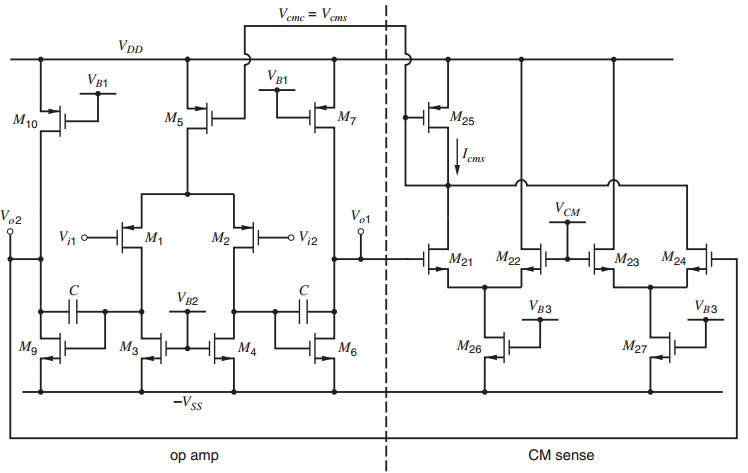
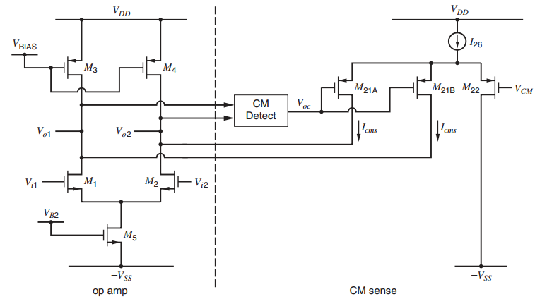
Fig. 12.18
Fantastic news! We've Found the answer you've been seeking!
Step by Step Answer:
One solution MIQ 400MA Voz 4H M9 M5 200...View the full answer

Answered By
GERALD KAMAU
non-plagiarism work, timely work and A++ work
6+ Reviews
11+ Question Solved
Related Book For 

Analysis and Design of Analog Integrated Circuits
ISBN: 978-0470245996
5th edition
Authors: Paul R. Gray, Paul J. Hurst Stephen H. Lewis, Robert G. Meyer
Question Posted:
