

Draw a section of a P&ID diagram for a vessel receiving a process liquid through an insulated
Question:
Draw a section of a P&ID diagram for a vessel receiving a process liquid through an insulated 4-in schedule-40 pipe. The purpose of the vessel is to store approximately 5 minutes of liquid volume and to provide “capacity” for a feed pump connected to the bottom of the vessel using a 6-in schedule-40 pipe. The diagram should include the following features:
The vessel is numbered V-1402 and the pump(s) are P-1407 A/B.
The discharge side of the pump is made of 4-in schedule-40 carbon steel pipe and all pipe is insulated.
A control valve is located in the discharge line of the pump, and a double block and bleed arrangement is used.
Both pumps and vessel have isolation (gate) valves.
The pumps should be equipped with drain lines that discharge to a chemical sewer.
The vessel is equipped with local pressure and temperature indicators.
The vessel has a pressure-relief valve set to 50 psig that discharges to a flare system.
The tank has a drain valve and a sampling valve, both of which are connected to the tank through separate 2-in schedule-40 CS lines.
The tank level is used to control the flow of liquid out of the tank by adjusting the setting of the control valve on the discharge side of the pump. The instrumentation is similar to that shown for V-104 in Figure 1.7.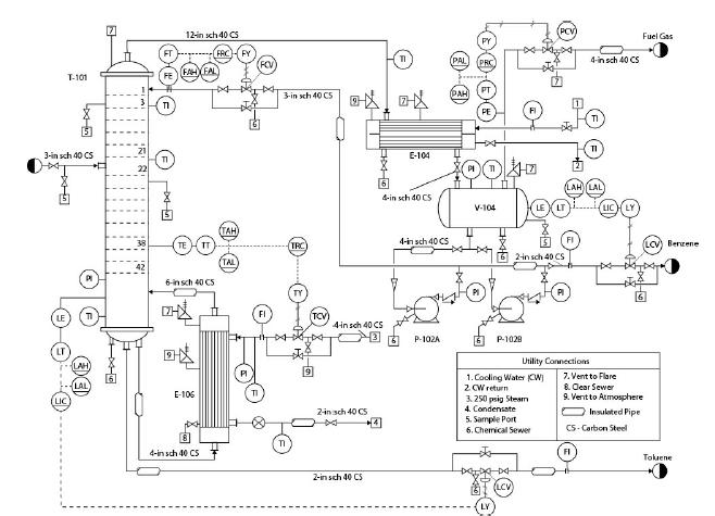
Step by Step Answer:

This question has not been answered yet.
You can Ask your question!

Analysis Synthesis And Design Of Chemical Processes
ISBN: 9780134177403
5th Edition
Authors: Richard Turton, Joseph Shaeiwitz, Debangsu Bhattacharyya, Wallace Whiting
