

Suppose we analyze the combinational logic of Figure 4.32 and determine that it can be separated into
Question:
Suppose we analyze the combinational logic of Figure 4.32 and determine that it can be separated into a sequence of six blocks, named A to F, having delays of 80, 30, 60, 50, 70, and 10 ps, respectively, illustrated as follows:
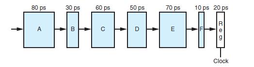
We can create pipelined versions of this design by inserting pipeline registers between pairs of these blocks. Different combinations of pipeline depth (how many stages) and maximum throughput arise, depending on where we insert the pipeline registers. Assume that a pipeline register has a delay of 20 ps.
A. Inserting a single register gives a two-stage pipeline. Where should the register be inserted to maximize throughput? What would be the throughput and latency?
B. Where should two registers be inserted to maximize the throughput of a three-stage pipeline? What would be the throughput and latency?
C. Where should three registers be inserted to maximize the throughput of a 4-stage pipeline? What would be the throughput and latency?
D. What is the minimum number of stages that would yield a design with the maximum achievable throughput? Describe this design, its throughput, and its latency.
Figure 4.32
Step by Step Answer:
This problem is an interesting exercise in trying to find the optimal balance among a set of partiti...View the full answer


Computer Systems A Programmers Perspective
ISBN: 9781292101767
3rd Global Edition
Authors: Randal E. Bryant, David R. O'Hallaron
