As shown in Fig. D9.1, a motor is coupled to an inertial load through a shaft. Significant
Question:
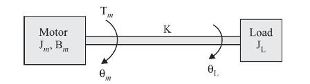
As shown in Fig. D9.1, a motor is coupled to an inertial load through a shaft. Significant variables and parameters involved in the system are as follows:
\[
\begin{aligned}
\mathrm{T}_{m}(t) & =\text { motor torque } \\
\mathrm{J}_{m} & =\text { motor inertia } \\
\mathrm{B}_{m} & =\text { motor friction coefficient } \\
\mathrm{J}_{\mathrm{L}} & =\text { Load inertia } \\
\mathrm{K} & =\text { spring constant of shaft } \\
\theta_{m}(t) & =\text { motor displacement } \\
\theta_{\mathrm{L}}(t) & =\text { load displacement }
\end{aligned}
\]
(a) Write torque equations describing system dynamics.
(b) Sketch state diagram (signal flow graph). Choose state variables
\[
\begin{aligned}
& x_{1}(t)=\theta_{m}(t)-\theta_{L}(t) \\
& x_{2}(t)=\dot{\theta}_{L}(t) \\
& x_{3}(t)=\dot{\theta}_{m}(t)
\end{aligned}
\]
(c) Obtain the transfer function model \(\frac{\theta_{m}(s)}{\mathrm{T}_{m}(s)}\) and \(\frac{\theta_{\mathrm{L}}(s)}{\mathrm{T}_{m}(s)}\)
Step by Step Answer:

This question has not been answered yet.
You can Ask your question!