Figure P9.8(a) shows the schematic diagram of a DC motor control system for controlling the print wheel
Question:
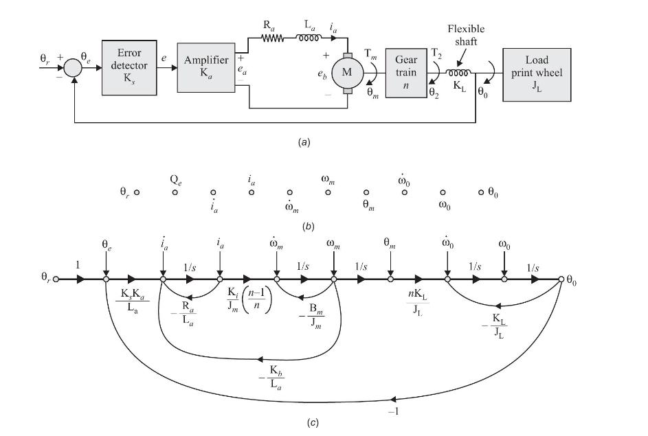
Figure P9.8(a) shows the schematic diagram of a DC motor control system for controlling the print wheel as load in an electronic word processor. The control system variables and parameters are defined as follows:
\(\mathrm{K}_{s}\) = gain of error detector (V/rad)
\(\mathrm{K}_{i}=\) torque constant
\(\mathrm{K}_{a}=\) amplifier gain
\(\mathrm{K}_{b}=\) back emf constant
\(n\) = gear turn ratio \(=\theta_{2} / \theta_{m}=T_{m} / T_{2}\)
\(\mathrm{B}_{m}=\) motor viscous-friction coefficient
\(\mathrm{J}_{m}=\) motor inertia
\(\mathrm{K}_{\mathrm{L}}=\) torsional spring constant of the motor shaft
\(\mathrm{J}_{\mathrm{L}}=\) load inertia
(a) Write equations describing system dynamics.
(b) Sketch signal flow graph with nodes as shown in Fig. P9.8(b).
Step by Step Answer:

This question has not been answered yet.
You can Ask your question!