

Consider the antenna control system of Fig. P7.5-5. This system is described in Problem 1.5-1. For this
Question:
Consider the antenna control system of Fig. P7.5-5. This system is described in Problem 1.5-1. For this problem, T = 0.05 s and D(z) = 1. It was shown in Problem 5.3-15 that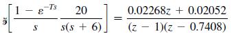
(a) Write the closed-loop system characteristic equation.
(b) Use the Routh–Hurwitz criterion to determine the range of K for stability.
(c) Check the results of part (b) using the Jury test.
(d) Determine the location of all roots of the characteristic equation in both the w-plane and the z-plane for the value of K 7 0 for which the system is marginally stable.
(e) Determine both the s-plane frequency and the w-plane frequency at which the system will oscillate when marginally stable, using the results of part (d).
(f) Show that the frequencies in part (e) satisfy.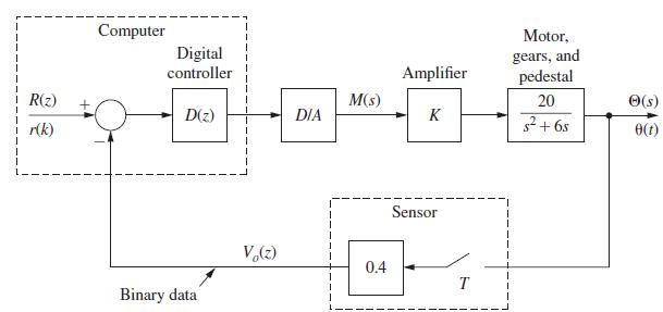
Problem 1.5-1
The antenna positioning system described in Section 1.5 is shown in Fig. P1.5–1. In this problem we consider the yaw angle control system, where w(t) is the yaw angle. Suppose that the gain of the power amplifier is 5 V/V, and that the gear ratio and the angle sensor (the shaft encoder and the data hold) are such that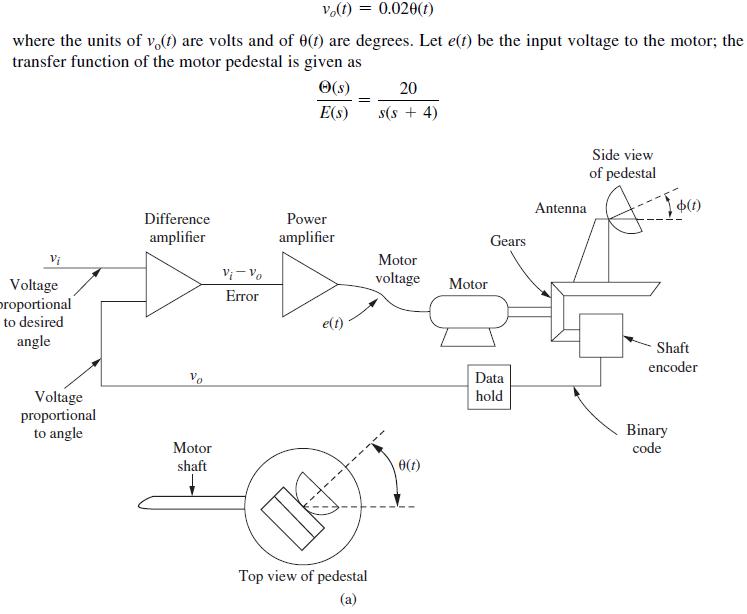
(a) With the system open loop [vo(t) is always zero], a unit step function of voltage is applied to the motor [E(s) = 1/s]. Consider only the steady-state response. Find the output angle θ(t) in degrees, and the angular velocity of the antenna pedestal, θ(t), in both degrees per second and rpm.
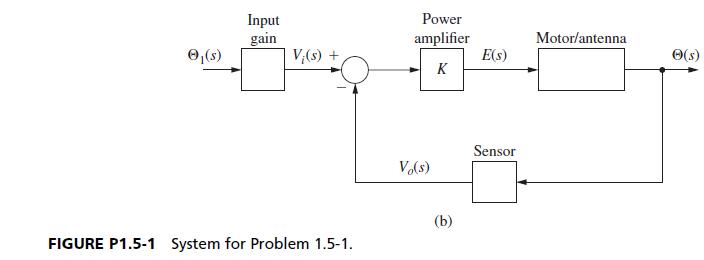
(b) The system block diagram is given in Fig. P1.5-1(b), with the angle signals shown in degrees and the voltages in volts. Add the required gains and the transfer functions to this block diagram.
(c) Make the changes necessary in the gains in part (b) such that the units of θ(t) are radians.
(d) A step input of θi(t) = 10° is applied at the system input at t = 0. Find the response w(t).
(e) The response in part (d) reaches steady state in approximately how many seconds?
Step by Step Answer:
a b c 1 KGz H 0 z 17408z 07408 0009072 Kz char eq z 000907...View the full answer


Digital Control System Analysis And Design
ISBN: 9780132938310
4th Edition
Authors: Charles Phillips, H. Nagle, Aranya Chakrabortty
