

Consider the satellite control system of Problem 5.3-14 and Fig. P5.3-14. Let D (z) = 1 ,
Question:
Consider the satellite control system of Problem 5.3-14 and Fig. P5.3-14. Let D(z) = 1 , T = 1 s, K = 2 , J = 0.1 , and H
k = 0.02 .
(a) Using the closed-loop transfer function, derive a discrete state model for the system.
(b) Derive a discrete state model for the plant from the plant transfer function. Then derive a state model for the closed-loop system by adding the feedback path and system input to a flow graph of the plant.
(c) Calculate the system transfer function from the state model found in part (b), to verify the state
model.
(d) Verify the results in part (c) using MATLAB.
Problem 5.3-14
Consider the satellite control system of Fig. P5.3-14. The unit of the attitude angle w(t) is degrees, and the range is 0 to 360º. The sensor gain is Hk = 0.05.
(a) Suppose that the input ranges for available A/Ds are 0 to 10 V, 0 to 20 V, 0 to 30 V, ±10 V, ±20 V, and ±30 V. Which range should be chosen? Why?
(b) The input signal r(t) is a voltage. Find the required value of r(t) to command the satellite attitude angle
w(t) to be 80º.
(c) Repeat parts (a) and (b) if the range of w(t) is ±180°.
(d) Let Gp(s) = 1>(Js2), the satellite transfer function. Find the system transfer function as a function of the transfer functions D(z), K, and so on.
(e) Evaluate the system transfer function for D(z) = 1, T = 0.5 s, K = 4, and J = 0.2.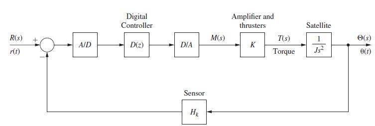
Step by Step Answer:
a From Problem 5314 xk1 Yz 10z1 Uz 2 18z 12 yk10 10xk 0 1 12 18 x ...View the full answer


Digital Control System Analysis And Design
ISBN: 9780132938310
4th Edition
Authors: Charles Phillips, H. Nagle, Aranya Chakrabortty
