

An older model Thunderbird car has three left (LA, LB, LC) and three right (RA, RB, RC)
Question:
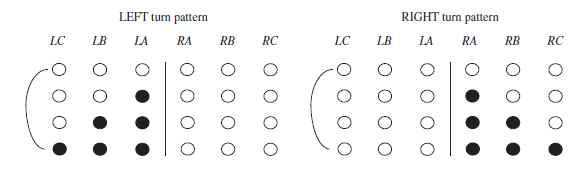
Design a Moore sequential circuit to control these lights. The circuit has three inputs: LEFT, RIGHT, and HAZ. LEFT and RIGHT come from the driver€™s turn signal switch and cannot be 1 at the same time. As indicated in the diagram, when LEFT = 1 the lights flash in a pattern LA on, LA and LB on, LA, LB, and LC on, all off; then the sequence repeats. When RIGHT = 1, a similar sequence appears on lights RA, RB, and RC, as indicated on the right side of the diagram. If a switch from LEFT to RIGHT (or vice versa) occurs in the middle of a flashing sequence, the circuit should immediately go to the IDLE (lights off) state and then start the new sequence. HAZ comes from the hazard switch, and when HAZ = 1, all six lights flash on and off in unison. HAZ takes precedence if LEFT or RIGHT is also on. Assume that a clock signal is available with a frequency equal to the desired flashing rate.
(a) Draw the state graph (eight states).
(b) Realize the circuit using six D flip-flops, and make a one-hot state assignment such that each flip-flop output drives one of the six lights directly. (You may use LogicAid.)
(c) Realize the circuit using three D flip-flops, using the guidelines from Section 1.7 to determine a suitable encoded state assignment. The tradeoff between more flip-flops and more gates in (b) and (c).
Step by Step Answer:
a Outputs LC LB LA RA RB RC b First assign LC Q 1 LB Q 2 LA Q 3 RA Q 4 RB Q 5 RC Q 6 So S 0 000000 S 1 001000 S 2 011000 etc This state machine has to...View the full answer


Digital Systems Design Using Verilog
ISBN: 978-1285051079
1st edition
Authors: Charles Roth, Lizy K. John, Byeong Kil Lee
