

Refer to Figure 7-17, where a 74HC190 has the input signals given in the timing diagram applied.
Question:
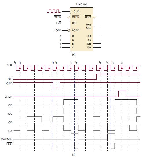
Refer to Figure 7-17, where a 74HC190 has the input signals given in the timing diagram applied. The parallel data inputs are permanently connected as 0111. Assume the counter is initially in the 0000 state, and determine the counter output waveforms.
Figure 7-17
Fantastic news! We've Found the answer you've been seeking!
Step by Step Answer:
Initially at to the counters FFs are all LOW Since the counter is enabled CTEN 0 and the count direc...View the full answer

Answered By
Muhammad Haroon
More than 3 years experience in teaching undergraduate and graduate level courses which includes Object Oriented Programming, Data Structures, Algorithms, Database Systems, Theory of Automata, Theory of Computation, Database Administration, Web Technologies etc.
3+ Reviews
10+ Question Solved
Related Book For 

Digital Systems Principles And Application
ISBN: 9780134220130
12th Edition
Authors: Ronald Tocci, Neal Widmer, Gregory Moss
Question Posted:
