

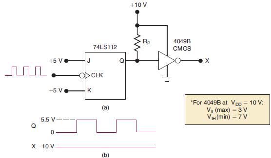
Refer to Figure 8-65(a), where a 74LS TTL output, Q, is driving a CMOS INVERTER operating at
Question:
Refer to Figure 8-65(a), where a 74LS TTL output, Q, is driving a CMOS INVERTER operating at VDD = 10 V. The waveforms at Q and X appear as shown in Figure 8-65(b). Which of the following is a possible reason why X stays HIGH?
(a) The 10-V supply is faulty.
(b) The pull-up resistor is too large.
(c) The 74LS112 output breaks down at well below 10 V and maintains a 5.5-V level in the HIGH state. This is in the indeterminate range for the CMOS input.
(d) The CMOS input is loading down the TTL output.
Figure 8-65
Fantastic news! We've Found the answer you've been seeking!
Step by Step Answer:
The correct answer is c The 74LS112 is a TTL inverter TTL inverters have a high output voltage of 25 ...View the full answer

Answered By
Wahome Michael
I am a CPA finalist and a graduate in Bachelor of commerce. I am a full time writer with 4 years experience in academic writing (essays, Thesis, dissertation and research). I am also a full time writer which assures you of my quality, deep knowledge of your task requirement and timeliness. Assign me your task and you shall have the best.
Thanks in advance
63+ Reviews
132+ Question Solved
Related Book For 

Digital Systems Principles And Application
ISBN: 9780134220130
12th Edition
Authors: Ronald Tocci, Neal Widmer, Gregory Moss
Question Posted:
