

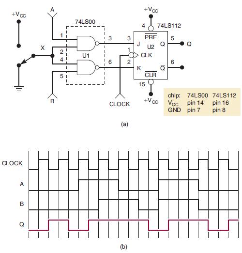
Refer to the circuit of Figure 5-102. Assume that the ICs are of the TTL logic family.
Question:
Refer to the circuit of Figure 5-102. Assume that the ICs are of the TTL logic family. The Q waveform was obtained when the circuit was tested with the input signals shown and with the switch in the “up” position; it is not correct. Consider the following list of faults, and for each indicate “yes” or “no” as to whether it could be the actual fault. Explain each response.
(a) Point X is always LOW due to a faulty switch.
(b) U1 pin 1 is internally shorted to VCC .
(c) The connection from U1-3 to U2-3 is open.
(d) There is a solder bridge between pins 6 and 7 of U1.
Figure 5-102
Fantastic news! We've Found the answer you've been seeking!
Step by Step Answer:

Answered By
Gowri Navada
Giving online tuition , teaching experience for about 20 years, coaching , etc
0 Reviews
10+ Question Solved
Related Book For 

Digital Systems Principles And Application
ISBN: 9780134220130
12th Edition
Authors: Ronald Tocci, Neal Widmer, Gregory Moss
Question Posted:
