

The keyboard entry circuit of Figure 9-16 is to be used as part of an electronic digital
Question:
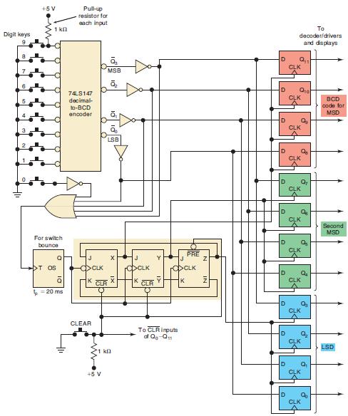
The keyboard entry circuit of Figure 9-16 is to be used as part of an electronic digital lock that operates as follows: when activated, an UNLOCK output goes HIGH. This HIGH is used to energize a solenoid that retracts a bolt and allows a door to be opened. To activate UNLOCK, the operator must press the CLEAR key and then enter the correct three-key sequence.
(a) Show how 74HC85 comparators and any other needed logic can be added to the keyboard entry circuit to produce the digital lock operation described above for a key sequence of CLEAR-3-5-8.
(b) Modify the circuit to activate an ALARM output if the operator enters something other than the correct three-key sequence.
Figure 9-16
Step by Step Answer:


Digital Systems Principles And Application
ISBN: 9780134220130
12th Edition
Authors: Ronald Tocci, Neal Widmer, Gregory Moss
