

The signals shown in Figure 4-79 are applied to the inputs of the circuit of Figure 4-32.
Question:
The signals shown in Figure 4-79 are applied to the inputs of the circuit of Figure 4-32. Suppose that there is an internal open circuit at Z1-4.
(a) What will a logic probe indicate at Z1-4?
(b) What dc voltage reading would you expect at Z1-4? (Remember that the ICs are TTL.)
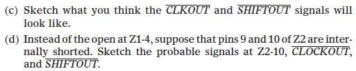
Figure 4-79
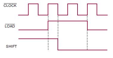
Figure 4-32
Step by Step Answer:

This question has not been answered yet.
You can Ask your question!
Related Book For 

Digital Systems Principles And Application
ISBN: 9780134220130
12th Edition
Authors: Ronald Tocci, Neal Widmer, Gregory Moss
Question Posted:
