

The synchronous data transmission system of Figures 9-32 and 9-33 is not working properly and the troubleshooting
Question:
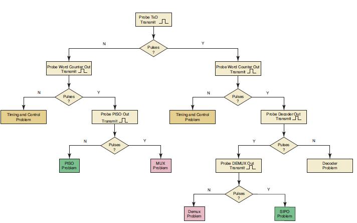
The synchronous data transmission system of Figures 9-32 and 9-33 is not working properly and the troubleshooting tree diagram of Figure 9-38 has been used to isolate the problem to the timing and control section of the receiver. Draw a troubleshooting tree diagram that will isolate the problem further to one of the four blocks in that section (FF1, Bit counter, Word counter, or FF2). Assume that all wires are connected as shown, with no wiring errors
Figure 9-32
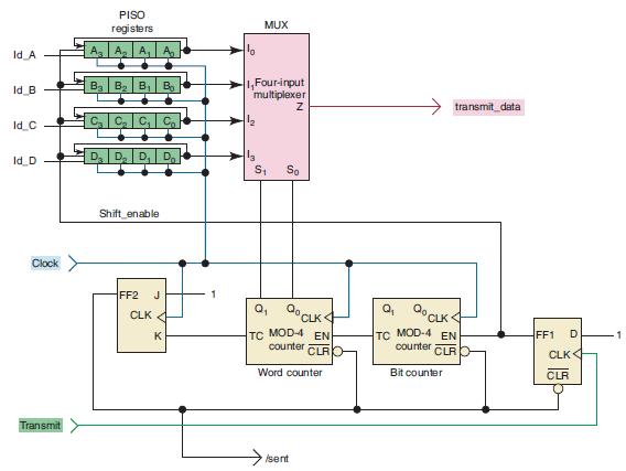
Figure 9-33
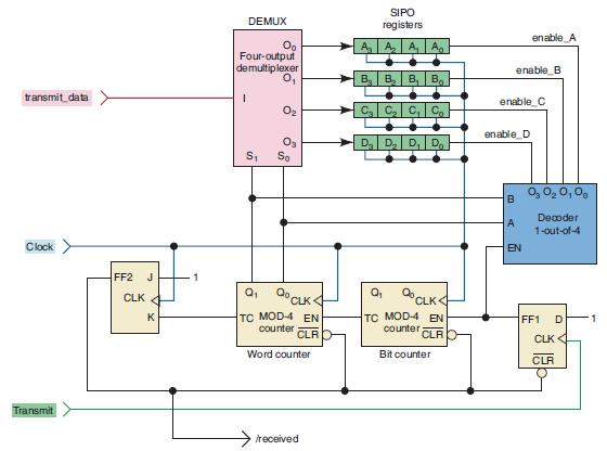
Figure 9-38
Step by Step Answer:

This question has not been answered yet.
You can Ask your question!
Related Book For 

Digital Systems Principles And Application
ISBN: 9780134220130
12th Edition
Authors: Ronald Tocci, Neal Widmer, Gregory Moss
Question Posted:
