

The addersubtractor circuit of Figure 3-45 has the following values for input select S and data inputs
Question:
The adder–subtractor circuit of Figure 3-45 has the following values for input select S and data inputs A and B:
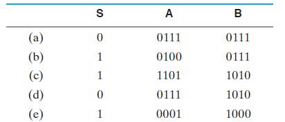
Figure 3-45
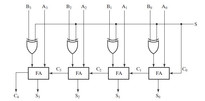
Determine, in each case, the values of the outputs S3, S2, S1, S0, and C4.
Fantastic news! We've Found the answer you've been seeking!
Step by Step Answer:
Certainly You have provided the inputs for an addersubtractor circuit and the respective truth table values along with the schematic diagram of the ci...View the full answer

Answered By
Fahmin Arakkal
Tutoring and Contributing expert question and answers to teachers and students.
Primarily oversees the Heat and Mass Transfer contents presented on websites and blogs.
Responsible for Creating, Editing, Updating all contents related Chemical Engineering in
latex language
8+ Reviews
22+ Question Solved
Related Book For 
Logic And Computer Design Fundamentals
ISBN: 9780133760637
5th Edition
Authors: M. Morris Mano, Charles Kime, Tom Martin
Question Posted:
