

The rotor shown in Fig. 9.44 (a) is balanced temporarily in a balancing machine by adding the
Question:
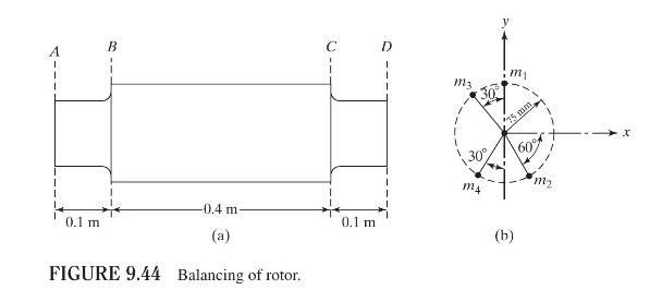
The rotor shown in Fig. 9.44 (a) is balanced temporarily in a balancing machine by adding the masses \(m_{1}=m_{2}=90 \mathrm{~g}\) in the plane \(A\) and \(m_{3}=m_{4}=90 \mathrm{~g}\) in the plane \(D\) at a radius of \(75 \mathrm{~mm}\), as shown in Fig. 9.44(b). If the rotor is permanently balanced by drilling holes at a radius of \(100 \mathrm{~mm}\) in planes \(B\) and \(C\), determine the position and amount of material to be removed from the rotor. Assume that the adjustable masses \(m_{1}\) to \(m_{4}\) will be removed from the planes \(A\) and \(D\).
Fantastic news! We've Found the answer you've been seeking!
Step by Step Answer:

Answered By
Muhammad Rehan
Enjoy testing and can find bugs easily and help improve the product quality.
10+ Reviews
10+ Question Solved
Related Book For 

Question Posted:
