

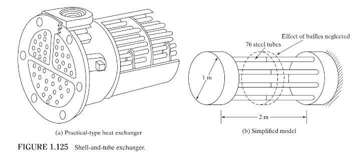
The shell-and-tube exchanger shown in Fig. 1.125 (a) can be modeled as shown in Fig. 1.125 (b)
Question:
The shell-and-tube exchanger shown in Fig. 1.125
(a) can be modeled as shown in Fig. 1.125
(b) for a simplified vibration analysis. Find the cross-sectional area of the tubes so that the total stiffness of the heat exchanger exceeds a value of \(200 \times 10^{6} \mathrm{~N} / \mathrm{m}\) in the axial direction and \(20 \times 10^{6} \mathrm{~N}-\mathrm{m} / \mathrm{rad}\) in the tangential direction. Assume that the tubes have the same length and cross section and are spaced uniformly.
Fantastic news! We've Found the answer you've been seeking!
Step by Step Answer:

Answered By
Ashish Jaiswal
I have completed B.Sc in mathematics and Master in Computer Science.
20+ Reviews
39+ Question Solved
Related Book For 
Question Posted:
