

In a transmission electron microscope, electrons, behaving as waves, are prepared in near-plane-wave quantum wave-packet states with
Question:
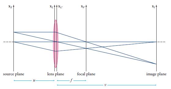
In a transmission electron microscope, electrons, behaving as waves, are prepared in near-plane-wave quantum wave-packet states with transverse sizes large compared to the object (“sample”) being imaged. The sample, placed in the source plane of Fig. 8.15, is sufficiently thin—with a transmission function t(x)—that the electron waves can pass through it, being diffracted in the process. The diffracted waves travel through the lens shown in Fig. 8.15 (the objective lens), then onward to and through a second lens, called the projector lens, which focuses them onto a fluorescent screen that shines with an energy flux proportional to the arriving electron flux. At least two lenses are needed, as in the simplest of optical microscopes and telescopes (Figs. 7.7 and 7.8), and for the same reason: to make images far larger than could be achieved with a single lens.
(a) The electrons all have the same kinetic energy E ∼ 200 keV, to within an energy spread △E1 ∼ eV. What is the wavelength λ of their nearly plane-wave quantum wave functions, and what is their fractional wavelength spread △λ/λ? Your answer for λ (∼a few picometers) is so small that electron microscopy can be used to study atoms and molecules. Contrast this with light’s million-fold longer wavelength ∼1μm, which constrains it to imaging objects a million times larger than atoms.
(b) Explain why the paraxial Fourier-optics formalism that we developed in Sec. 8.5 can be used without change to analyze this electron microscope. This is true even though the photons of an ordinary microscope are in states with mean occupation numbers η huge compared to unity while the electrons have η ≪ 1, and the photons have zero rest mass while the electrons have finite rest mass m with roughly the same magnitude as their kinetic energies, E ∼ mc2.
(c) Suppose that each magnetic lens in the electron microscope is made of two transverse magnetic quadrupoles, as described in Sec. 7.4.2. Show that, although these quadrupoles are far from axisymmetric, their combined influence on each electron’s wave function is given by the axisymmetric thin-lens point-spread function (8.29) with focal length (7.66), to within the accuracy of the analysis of Sec. 7.4.2. [In practice, higher-order corrections make the combined lens sufficiently nonaxisymmetric that electron microscopes do not use this type of magnetic lens. Instead they use a truly axisymmetric lens in which the magnetic field lines lie in planes of constant azimuthal angle ∅, and the field lines first bend the electron trajectories into helices (give them motion in the ∅ direction), then bend them radially, and then undo the helical motion.]
(d) By appropriate placement of the projector lens, the microscope can produce, in fluorescing plane, either a vastly enlarged image of the source-plane sample, |t(x)|2, or a large image of the modulus of that object’s Fourier transform (the object’s diffraction pattern), |t̃(k)|2. Explain how each of these is achieved.
Fig. 7.7
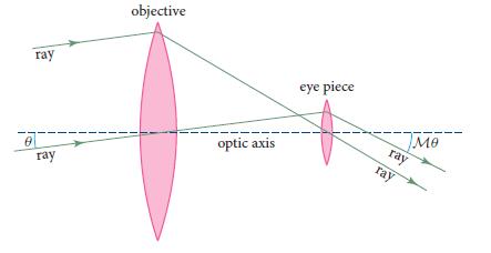
Fig. 7.8
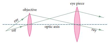
Fig. 8.15
Step by Step Answer:


Modern Classical Physics Optics Fluids Plasmas Elasticity Relativity And Statistical Physics
ISBN: 9780691159027
1st Edition
Authors: Kip S. Thorne, Roger D. Blandford
