

Elevator Controller The block diagram for an elevator controller for a two-floorelevator follows. The inputs FB1 and
Question:
Elevator Controller
The block diagram for an elevator controller for a two-floorelevator follows.
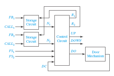
The inputs FB1 and FB2 are 1 when someone in the elevatorpresses the first and secondfloor buttons, respectively. The inputs CALL1 and CALL2 are 1 whensomeone on the firstor second floor presses the elevator call button. The input FS1 andFS2 are 1 when theelevator is at the first floor or second floor landing. The outputUP turns on the motor toraise the elevator car; DOWN turns on the motor to lower theelevator. If neither UP norDOWN is 1, the elevator will not move. R1 and R2 reset latches(described below); andwhen DO goes to 1, the elevator door opens. After the door opensand remains open for areasonable length of time (determined by the door controllermechanism), the doorcontroller mechanism closes the door and set DC=1. Assume that allinput signals areproperly synchronized with the system clock.
(a) If we were to realize a control circuit that responded to allthe inputs FB1, FB2, CALL1,CALL2, FS1, FS2 and DC, we would need to implement logic equationswith nine andmore variables (seven input plus at least two state variables).
However, if we combine the signal FBi and CALLi into a signal Ni (i= 1 or 2) thatindicates that the elevator is needed on the specific floor, we canreduce the number ofinputs into the control circuit. In addition, if the signal Ni isstored so that a single pulseon FBi or CALLi will set N1 to 1 until control circuit clears it,then the control circuit willbe simplified further. Using ONE D-FF and a minimum number of addedgates,design a storage circuit that will have an output 1 when eitherinput (FBi or CALLi)become 1 and will stay 1 until reset with a signal Ri
(b) Using the signals N1 and N2 that indicate that the elevator isneeded on the first orsecond floor (to deliver a passenger or pick one up or both),derive a state graph for theelevator controller. (Only four states are needed.)
(c) Realize the circuit for elevator controller in (b).
Expert Answer:
a To simplify the control circuit we can combine the signals FBi and CALLi into a signal Ni Addition... View the full answer


Digital Systems Design Using Verilog
ISBN: 978-1285051079
1st edition
Authors: Charles Roth, Lizy K. John, Byeong Kil Lee
