Clock Timer and DC Motor Speed Control Objectives 1. To simulate and operate an astable multivibrator. 2.
Question:
Clock Timer and DC Motor Speed Control
Objectives
1. To simulate and operate an astable multivibrator.
2. To determine the timer frequency by mathematicalcalculations, by using a graph, and by using test instruments.
3. To use an astable multivibrator in PWM generation and DCmotor speed control.
Introduction
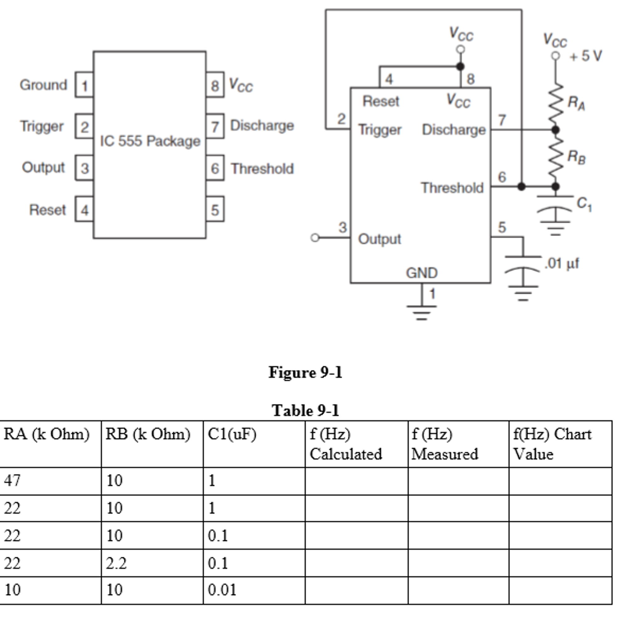
Clock signals are square-edged rectangular signals thatcontinually change back and forth between the two logic states.Many types of digital circuits require clock signals in order tofunction. Clock signals are considered the heartbeat ofmicroprocessor-based devices; they provide the pulses necessary totime and control the proper sequencing of all events throughout thecomputing system. A circuit that produces a continuous rectangularsignal is called an astable (free-running) multivibrator. Anastable multivibrator, using a 555 timer chip, is shown in Figure9-1. With only two resistors and a capacitor, the 555 IC canproduce a highly accurate rectangular signal.
Procedure
Step 1 Draw the circuit shown in Figure 9-1 in Multiim. Use thecomponent values listed on the first line of Table 9-1.
Background Information
The frequency of the timer depends on how rapidly the internalcomponents of the 555 IC turn on and off. This rate is determinedby the values of the components connected externally to the IC. Thefrequency of the output can be calculated by the following formula: 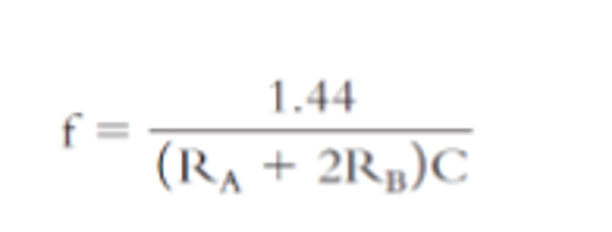
Step 2 Using the formula above, calculate f and record youranswer in Table 9-1. Step 3 Using the oscilloscope, measure fout (frequency out) atoutput pin 3 and record it in Table 9-1. Step 4 Repeat Steps 2 and 3 for the remaining values of RA, RB, andC1, given in the table. Background Information?Frequency Chart Figure 9-2 is a quick reference chart that provides a way ofdetermining which combination of external resistance andcapacitance values generate a desired frequency. To use the chart:1. Select the desired frequency on the bottom horizontal line onthe chart. 2. Follow this frequency line upward until it intersectsan available capacitor value. 3. Read the combined resistance valuefor RA and 2RB from the nearest diagonal line.
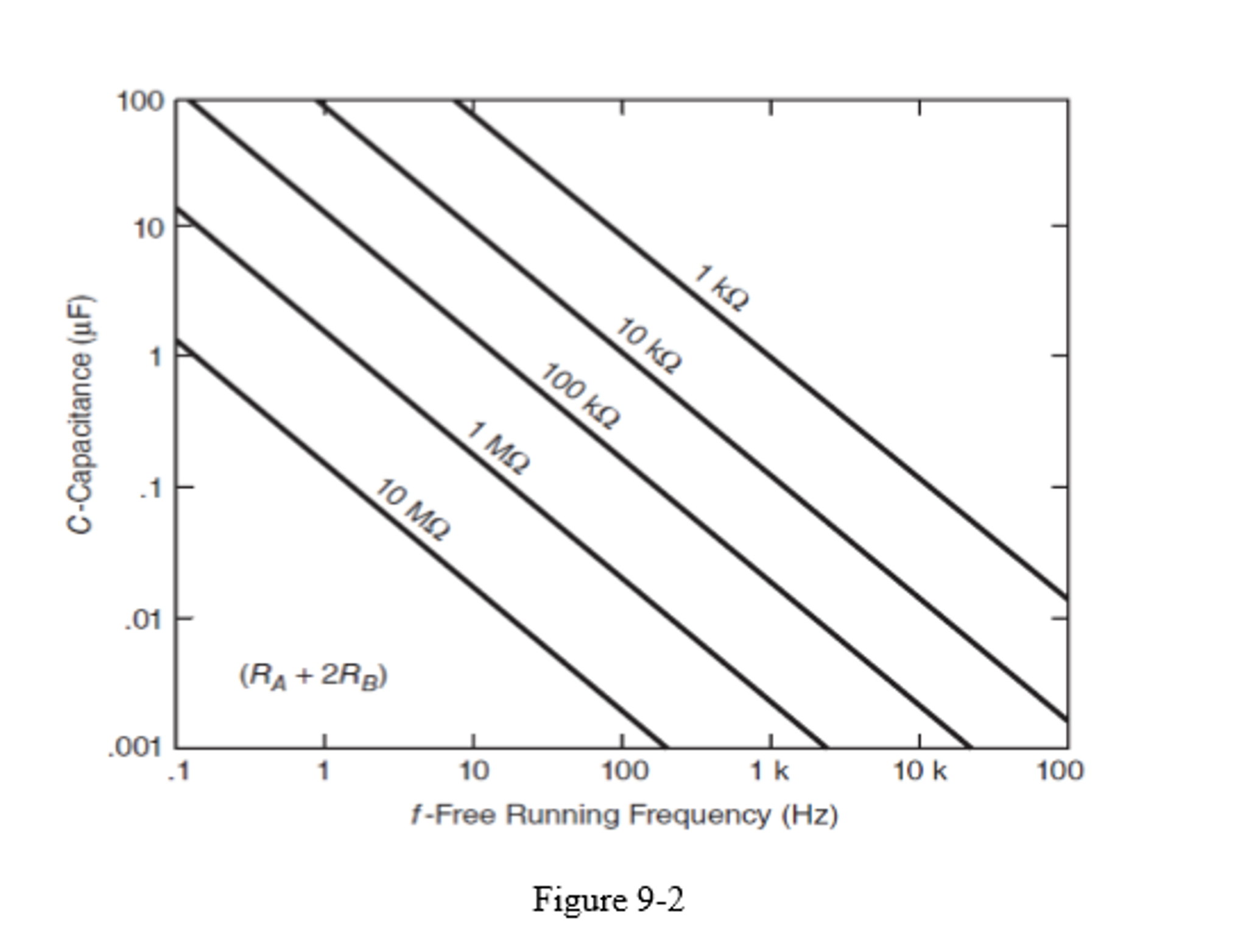
Step 4 Using the chart, find the astable multivibrator frequencyfor each of the RA, RB, and C1 values listed in Table 9-1. Enterthe answer in the right-hand column (headed ?ChartValues?). DC Motor Speed Control Using PWM and IC 555 PWM (Pulse Width Modulation) can be used to change the average of aDC voltage by changing the ON/OFF ratio of a pulse signal. Theratio of the ON time to the period of the pulse signal is DutyCycle and is defined as follows: Duty Cycle= [(ON time)/(Period of the pulse)] x 100 Step 5 Use the figure 9-3 to draw and simulate 555 PWM generator inMultisim. The ratio of the ON time to OFF time can be adjustedusing the potentiometer in the circuit. Use oscilloscope andmeasure the frequency of the output signal of the 555 IC. Draw thewaveform of 555 output and drain of the MOSFET transistor in thespace below:
555 Output: ?............................................................................. Transistor Output:?............................................................. Step 6 Use DVM and measure the voltage across the DC motor. Change theduty cycle and fill out the following table. 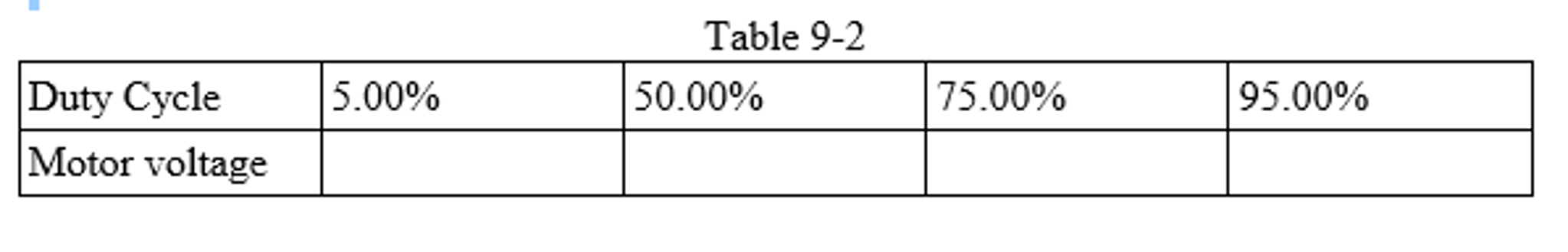
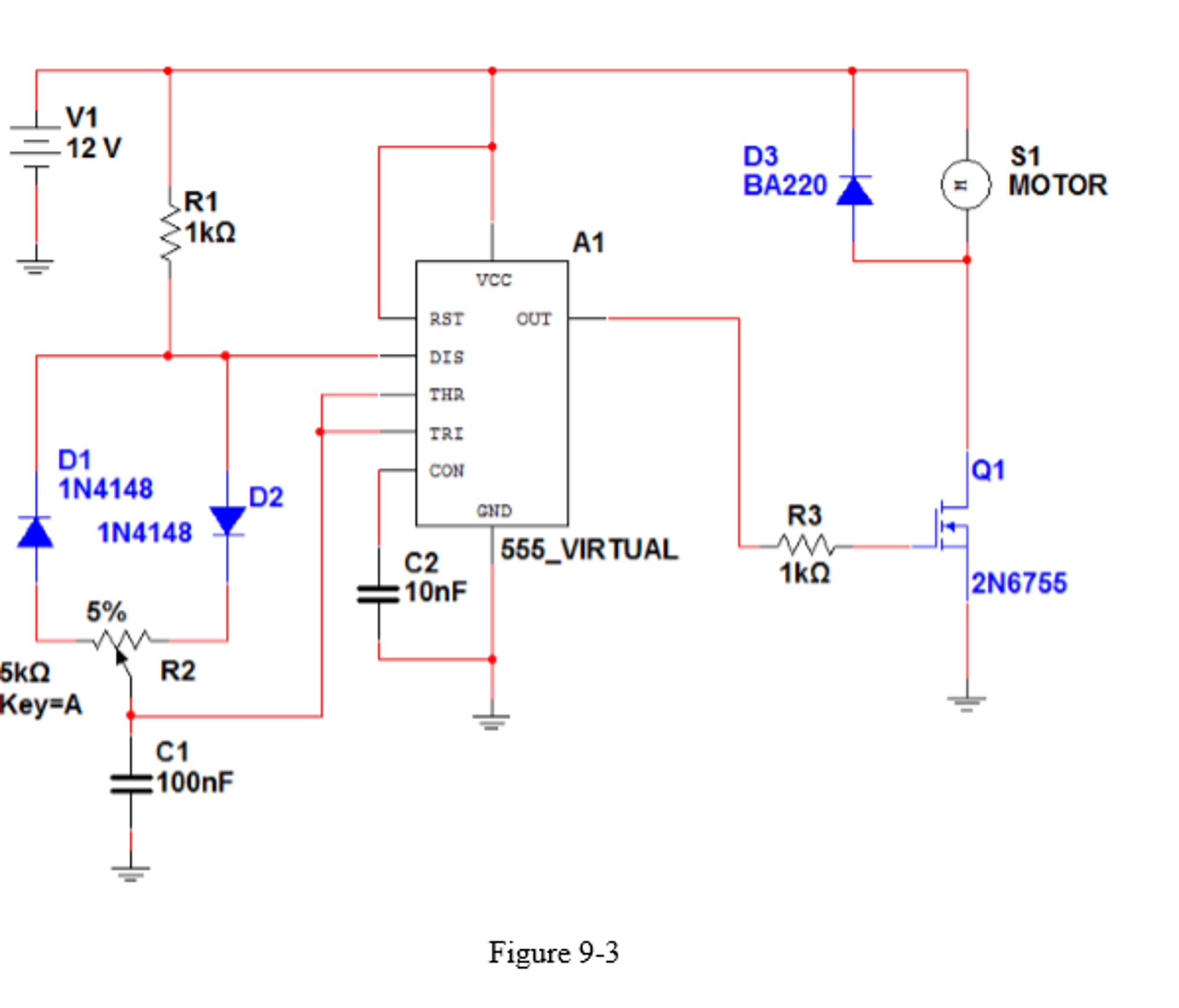
Experiment Questions 1. A circuit that produces a continuous rectangular signal iscalled a(n) ?....... multivibrator. 2. The frequency of the 555 IC timer depends on whatfactors? 3. What activates the 555 IC timer? 4. What are clock signals used for? 5. Using the formula f = 1.44/(RA+2RB)C, determine the frequency ofa 555 IC timer when the component values are asfollows: RA = 2K Ohms, RB = 15K Ohms, C = 0.1microF, f=.............. 6. Suppose a frequency of 1100Hz is desired and a 0.001microFcapacitor is available. Using the chart in Figure 9-2, determinethe required combined values of RA and RB. 7- What is the purpose of diodes D1, D2 and D3 in figure 9-3?
Expert Answer: