

Multiplexer is a combinational circuit that has maximum of 2 data inputs, 'n' selection lines and...
Fantastic news! We've Found the answer you've been seeking!
Question:
Transcribed Image Text:
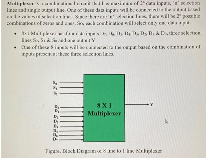
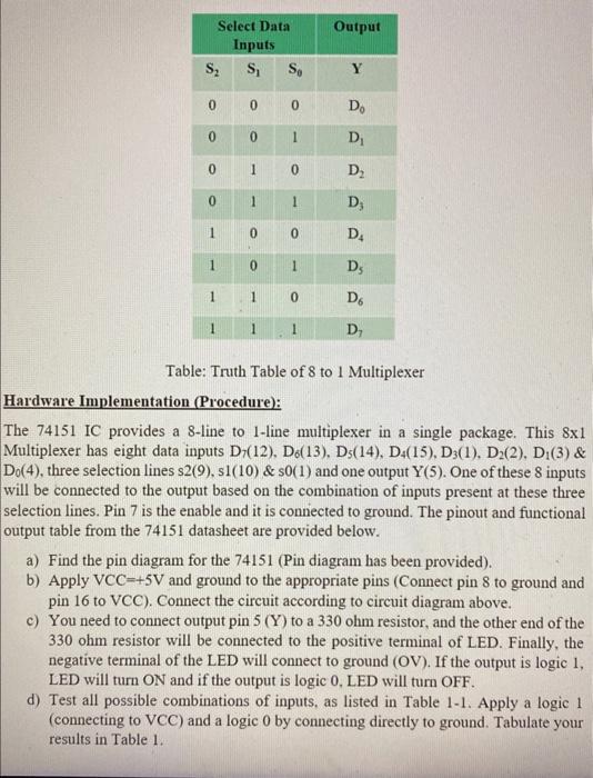
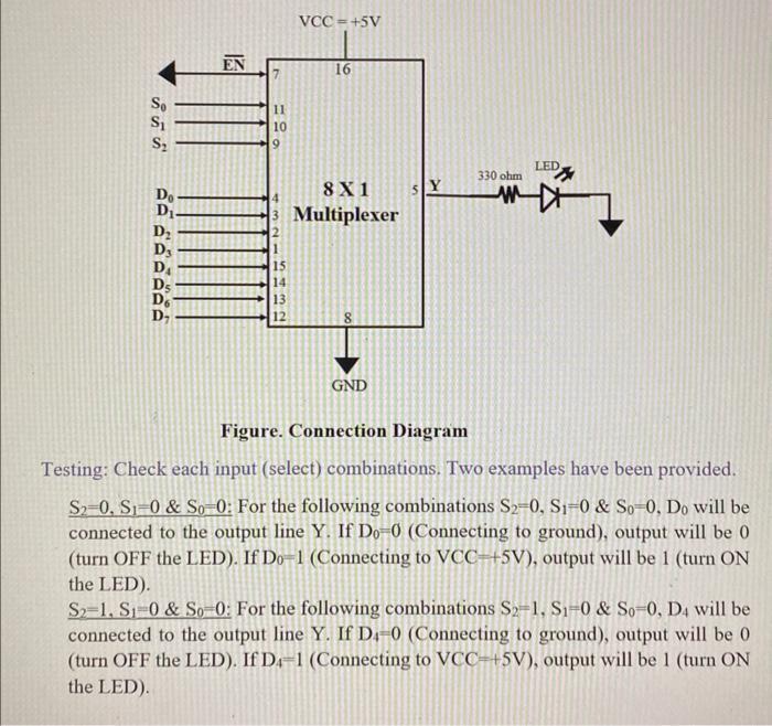
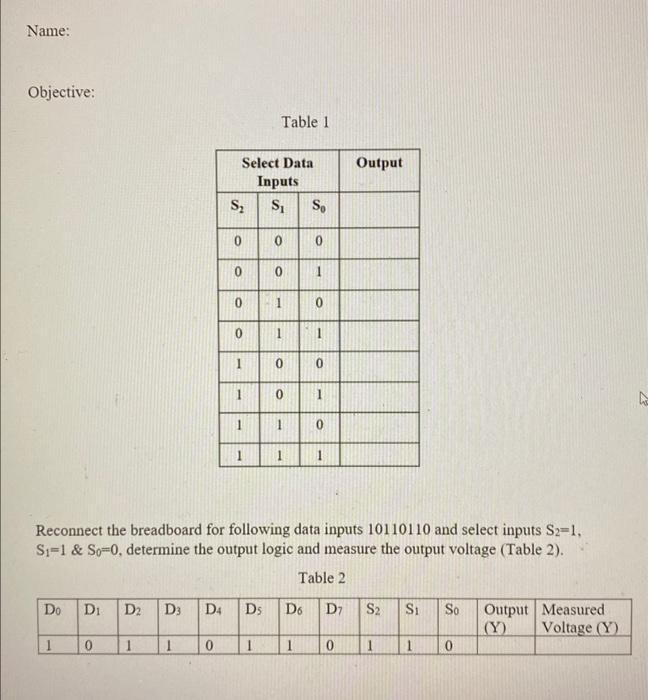
Multiplexer is a combinational circuit that has maximum of 2" data inputs, 'n' selection lines and single output line. One of these data inputs will be connected to the output based on the values of selection lines. Since there are 'n' selection lines, there will be 2" possible combinations of zeros and ones. So, each combination will select only one data input. • 8x1 Multiplexer has four data inputs D7, D6, Ds, D4, D3, D2, D1 & Do, three selection lines S2, S1 & So and one output Y. . One of these 8 inputs will be connected to the output based on the combination of inputs present at these three selection lines. So S₁ S₂ Do- D₁. D₂ Dy D₁ Ds Do D₂ 8X1 Multiplexer Figure. Block Diagram of 8 line to 1 line Multiplexer 21 S₂ 0 0 0 0 1 Select Data Inputs S₁ 1 1 1 0 0 1 1 0 0 So 0 1 0 1 0 1 1 0 1 Output Y Do D₁ D₂ D₂ D₁ Ds D6 D₁ Table: Truth Table of 8 to 1 Multiplexer Hardware Implementation (Procedure): The 74151 IC provides a 8-line to 1-line multiplexer in a single package. This 8x1 Multiplexer has eight data inputs D7(12). De(13). Ds(14), D4(15), D3(1), D2(2), D1(3) & Do(4), three selection lines s2(9), s1(10) & s0(1) and one output Y(5). One of these 8 inputs will be connected to the output based on the combination of inputs present at these three selection lines. Pin 7 is the enable and it is connected to ground. The pinout and functional output table from the 74151 datasheet are provided below. a) Find the pin diagram for the 74151 (Pin diagram has been provided). b) Apply VCC-+5V and ground to the appropriate pins (Connect pin 8 to ground and pin 16 to VCC). Connect the circuit according to circuit diagram above. c) You need to connect output pin 5 (Y) to a 330 ohm resistor, and the other end of the 330 ohm resistor will be connected to the positive terminal of LED. Finally, the negative terminal of the LED will connect to ground (OV). If the output is logic 1, LED will turn ON and if the output is logic 0, LED will turn OFF. d) Test all possible combinations of inputs, as listed in Table 1-1. Apply a logic 1 (connecting to VCC) and a logic 0 by connecting directly to ground. Tabulate your results in Table 1. Se S₁ S₂ Do D₁. D₂ D3 D₁ De EN 11 10 9 15 14 13 12 VCC=+5V 16 8X1 Multiplexer GND 330 ohm LED Figure. Connection Diagram Testing: Check each input (select) combinations. Two examples have been provided. S2-0, S1-0 & So-0: For the following combinations S2-0, S1-0 & So-0, Do will be connected to the output line Y. If Do-0 (Connecting to ground), output will be 0 (turn OFF the LED). If Do-1 (Connecting to VCC-+5V), output will be 1 (turn ON the LED). S2-1, S1-0 & So-0: For the following combinations S2-1, S1-0 & So-0, D4 will be connected to the output line Y. If D4-0 (Connecting to ground), output will be 0 (turn OFF the LED). If D4-1 (Connecting to VCC-+5V), output will be 1 (turn ON the LED). Name: Objective: Do Di D₂ D3 1 1 Select Data Inputs S₁ S₂ 0 0 0 0 0 1 1 1 1 D4 Ds Table 1 1 0 0 1 1 0 0 1 1 So 0 1 0 1 Reconnect the breadboard for following data inputs 10110110 and select inputs S2-1, Si=1 & So-0, determine the output logic and measure the output voltage (Table 2). Table 2 0 1 0 1 Output D6 D7 S2 Si 0 So 0 Output Measured. (Y) Voltage (Y) h Multiplexer is a combinational circuit that has maximum of 2" data inputs, 'n' selection lines and single output line. One of these data inputs will be connected to the output based on the values of selection lines. Since there are 'n' selection lines, there will be 2" possible combinations of zeros and ones. So, each combination will select only one data input. • 8x1 Multiplexer has four data inputs D7, D6, Ds, D4, D3, D2, D1 & Do, three selection lines S2, S1 & So and one output Y. . One of these 8 inputs will be connected to the output based on the combination of inputs present at these three selection lines. So S₁ S₂ Do- D₁. D₂ Dy D₁ Ds Do D₂ 8X1 Multiplexer Figure. Block Diagram of 8 line to 1 line Multiplexer 21 S₂ 0 0 0 0 1 Select Data Inputs S₁ 1 1 1 0 0 1 1 0 0 So 0 1 0 1 0 1 1 0 1 Output Y Do D₁ D₂ D₂ D₁ Ds D6 D₁ Table: Truth Table of 8 to 1 Multiplexer Hardware Implementation (Procedure): The 74151 IC provides a 8-line to 1-line multiplexer in a single package. This 8x1 Multiplexer has eight data inputs D7(12), De(13). Ds(14), D4(15), D3(1), D2(2), D1(3) & Do(4), three selection lines s2(9), sl(10) & s0(1) and one output Y(5). One of these 8 inputs will be connected to the output based on the combination of inputs present at these three selection lines. Pin 7 is the enable and it is connected to ground. The pinout and functional output table from the 74151 datasheet are provided below. a) Find the pin diagram for the 74151 (Pin diagram has been provided). b) Apply VCC-+5V and ground to the appropriate pins (Connect pin 8 to ground and pin 16 to VCC). Connect the circuit according to circuit diagram above. c) You need to connect output pin 5 (Y) to a 330 ohm resistor, and the other end of the 330 ohm resistor will be connected to the positive terminal of LED. Finally, the negative terminal of the LED will connect to ground (OV). If the output is logic 1, LED will turn ON and if the output is logic 0, LED will turn OFF. d) Test all possible combinations of inputs, as listed in Table 1-1. Apply a logic 1 (connecting to VCC) and a logic 0 by connecting directly to ground. Tabulate your results in Table 1. Se S₁ S₂ Do D₁. D₂ D3 D₁ De EN 11 10 9 15 14 13 12 VCC=+5V 16 8X1 Multiplexer GND 330 ohm LED Figure. Connection Diagram Testing: Check each input (select) combinations. Two examples have been provided. S2-0, S1-0 & So-0: For the following combinations S2-0, S1-0 & So-0, Do will be connected to the output line Y. If Do-0 (Connecting to ground), output will be 0 (turn OFF the LED). If Do-1 (Connecting to VCC-+5V), output will be 1 (turn ON the LED). S2-1, S1-0 & So-0: For the following combinations S2-1, S1-0 & So-0, D4 will be connected to the output line Y. If D-0 (Connecting to ground), output will be 0 (turn OFF the LED). If D4-1 (Connecting to VCC-+5V), output will be 1 (turn ON the LED). Name: Objective: Do Di D₂ D3 1 1 Select Data Inputs S₁ S₂ 0 0 0 0 0 1 1 1 1 D4 Ds Table 1 1 0 0 1 1 0 0 1 1 So 0 1 0 1 Reconnect the breadboard for following data inputs 10110110 and select inputs S2-1, Si=1 & So-0, determine the output logic and measure the output voltage (Table 2). Table 2 0 1 0 1 Output D6 D7 S2 Si 0 So 0 Output Measured. (Y) Voltage (Y) h Multiplexer is a combinational circuit that has maximum of 2" data inputs, 'n' selection lines and single output line. One of these data inputs will be connected to the output based on the values of selection lines. Since there are 'n' selection lines, there will be 2" possible combinations of zeros and ones. So, each combination will select only one data input. • 8x1 Multiplexer has four data inputs D7, D6, Ds, D4, D3, D2, D1 & Do, three selection lines S2, S1 & So and one output Y. . One of these 8 inputs will be connected to the output based on the combination of inputs present at these three selection lines. So S₁ S₂ Do- D₁. D₂ Dy D₁ Ds Do D₂ 8X1 Multiplexer Figure. Block Diagram of 8 line to 1 line Multiplexer 21 S₂ 0 0 0 0 1 Select Data Inputs S₁ 1 1 1 0 0 1 1 0 0 So 0 1 0 1 0 1 1 0 1 Output Y Do D₁ D₂ D₂ D₁ Ds D6 D₁ Table: Truth Table of 8 to 1 Multiplexer Hardware Implementation (Procedure): The 74151 IC provides a 8-line to 1-line multiplexer in a single package. This 8x1 Multiplexer has eight data inputs D7(12). De(13), Ds(14), D4(15), D3(1), D2(2), D1(3) & Do(4), three selection lines s2(9), sl(10) & s0(1) and one output Y(5). One of these 8 inputs will be connected to the output based on the combination of inputs present at these three selection lines. Pin 7 is the enable and it is connected to ground. The pinout and functional output table from the 74151 datasheet are provided below. a) Find the pin diagram for the 74151 (Pin diagram has been provided). b) Apply VCC-+5V and ground to the appropriate pins (Connect pin 8 to ground and pin 16 to VCC). Connect the circuit according to circuit diagram above. c) You need to connect output pin 5 (Y) to a 330 ohm resistor, and the other end of the 330 ohm resistor will be connected to the positive terminal of LED. Finally, the negative terminal of the LED will connect to ground (OV). If the output is logic 1, LED will turn ON and if the output is logic 0, LED will turn OFF. d) Test all possible combinations of inputs, as listed in Table 1-1. Apply a logic 1 (connecting to VCC) and a logic 0 by connecting directly to ground. Tabulate your results in Table 1. Se S₁ S₂ Do D₁. D₂ D3 D₁ De EN 11 10 9 15 14 13 12 VCC=+5V 16 8X1 Multiplexer GND 330 ohm LED Figure. Connection Diagram Testing: Check each input (select) combinations. Two examples have been provided. S2-0. S1-0 & So-0: For the following combinations S2-0, S1-0 & So-0, Do will be connected to the output line Y. If Do-0 (Connecting to ground), output will be 0 (turn OFF the LED). If Do-1 (Connecting to VCC-+5V), output will be 1 (turn ON the LED). S2-1, S1-0 & So-0: For the following combinations S2-1, S1-0 & So-0, D4 will be connected to the output line Y. If D-0 (Connecting to ground), output will be 0 (turn OFF the LED). If D4-1 (Connecting to VCC-+5V), output will be 1 (turn ON the LED). Name: Objective: Do Di D₂ D3 1 1 Select Data Inputs S₁ S₂ 0 0 0 0 0 1 1 1 1 D4 Ds Table 1 1 0 0 1 1 0 0 1 1 So 0 1 0 1 Reconnect the breadboard for following data inputs 10110110 and select inputs S2-1, Si=1 & So-0, determine the output logic and measure the output voltage (Table 2). Table 2 0 1 0 1 Output D6 D7 S2 Si 0 So 0 Output Measured. (Y) Voltage (Y) h Multiplexer is a combinational circuit that has maximum of 2" data inputs, 'n' selection lines and single output line. One of these data inputs will be connected to the output based on the values of selection lines. Since there are 'n' selection lines, there will be 2" possible combinations of zeros and ones. So, each combination will select only one data input. • 8x1 Multiplexer has four data inputs D7, D6, Ds, D4, D3, D2, D1 & Do, three selection lines S2, S1 & So and one output Y. . One of these 8 inputs will be connected to the output based on the combination of inputs present at these three selection lines. So S₁ S₂ Do- D₁. D₂ Dy D₁ Ds Do D₂ 8X1 Multiplexer Figure. Block Diagram of 8 line to 1 line Multiplexer 21 S₂ 0 0 0 0 1 Select Data Inputs S₁ 1 1 1 0 0 1 1 0 0 So 0 1 0 1 0 1 1 0 1 Output Y Do D₁ D₂ D₂ D₁ Ds D6 D₁ Table: Truth Table of 8 to 1 Multiplexer Hardware Implementation (Procedure): The 74151 IC provides a 8-line to 1-line multiplexer in a single package. This 8x1 Multiplexer has eight data inputs D7(12). De(13). Ds(14), D4(15), D3(1), D2(2), D1(3) & Do(4), three selection lines s2(9), s1(10) & s0(1) and one output Y(5). One of these 8 inputs will be connected to the output based on the combination of inputs present at these three selection lines. Pin 7 is the enable and it is connected to ground. The pinout and functional output table from the 74151 datasheet are provided below. a) Find the pin diagram for the 74151 (Pin diagram has been provided). b) Apply VCC-+5V and ground to the appropriate pins (Connect pin 8 to ground and pin 16 to VCC). Connect the circuit according to circuit diagram above. c) You need to connect output pin 5 (Y) to a 330 ohm resistor, and the other end of the 330 ohm resistor will be connected to the positive terminal of LED. Finally, the negative terminal of the LED will connect to ground (OV). If the output is logic 1, LED will turn ON and if the output is logic 0, LED will turn OFF. d) Test all possible combinations of inputs, as listed in Table 1-1. Apply a logic 1 (connecting to VCC) and a logic 0 by connecting directly to ground. Tabulate your results in Table 1. Se S₁ S₂ Do D₁. D₂ D3 D₁ De EN 11 10 9 15 14 13 12 VCC=+5V 16 8X1 Multiplexer GND 330 ohm LED Figure. Connection Diagram Testing: Check each input (select) combinations. Two examples have been provided. S2-0, S1-0 & So-0: For the following combinations S2-0, S1-0 & So-0, Do will be connected to the output line Y. If Do-0 (Connecting to ground), output will be 0 (turn OFF the LED). If Do-1 (Connecting to VCC-+5V), output will be 1 (turn ON the LED). S2-1, S1-0 & So-0: For the following combinations S2-1, S1-0 & So-0, D4 will be connected to the output line Y. If D4-0 (Connecting to ground), output will be 0 (turn OFF the LED). If D4-1 (Connecting to VCC-+5V), output will be 1 (turn ON the LED). Name: Objective: Do Di D₂ D3 1 1 Select Data Inputs S₁ S₂ 0 0 0 0 0 1 1 1 1 D4 Ds Table 1 1 0 0 1 1 0 0 1 1 So 0 1 0 1 Reconnect the breadboard for following data inputs 10110110 and select inputs S2-1, Si=1 & So-0, determine the output logic and measure the output voltage (Table 2). Table 2 0 1 0 1 Output D6 D7 S2 Si 0 So 0 Output Measured. (Y) Voltage (Y) h Multiplexer is a combinational circuit that has maximum of 2" data inputs, 'n' selection lines and single output line. One of these data inputs will be connected to the output based on the values of selection lines. Since there are 'n' selection lines, there will be 2" possible combinations of zeros and ones. So, each combination will select only one data input. • 8x1 Multiplexer has four data inputs D7, D6, Ds, D4, D3, D2, D1 & Do, three selection lines S2, S1 & So and one output Y. . One of these 8 inputs will be connected to the output based on the combination of inputs present at these three selection lines. So S₁ S₂ Do- D₁. D₂ Dy D₁ Ds Do D₂ 8X1 Multiplexer Figure. Block Diagram of 8 line to 1 line Multiplexer 21 S₂ 0 0 0 0 1 Select Data Inputs S₁ 1 1 1 0 0 1 1 0 0 So 0 1 0 1 0 1 1 0 1 Output Y Do D₁ D₂ D₂ D₁ Ds D6 D₁ Table: Truth Table of 8 to 1 Multiplexer Hardware Implementation (Procedure): The 74151 IC provides a 8-line to 1-line multiplexer in a single package. This 8x1 Multiplexer has eight data inputs D7(12), De(13). Ds(14), D4(15), D3(1), D2(2), D1(3) & Do(4), three selection lines s2(9), sl(10) & s0(1) and one output Y(5). One of these 8 inputs will be connected to the output based on the combination of inputs present at these three selection lines. Pin 7 is the enable and it is connected to ground. The pinout and functional output table from the 74151 datasheet are provided below. a) Find the pin diagram for the 74151 (Pin diagram has been provided). b) Apply VCC-+5V and ground to the appropriate pins (Connect pin 8 to ground and pin 16 to VCC). Connect the circuit according to circuit diagram above. c) You need to connect output pin 5 (Y) to a 330 ohm resistor, and the other end of the 330 ohm resistor will be connected to the positive terminal of LED. Finally, the negative terminal of the LED will connect to ground (OV). If the output is logic 1, LED will turn ON and if the output is logic 0, LED will turn OFF. d) Test all possible combinations of inputs, as listed in Table 1-1. Apply a logic 1 (connecting to VCC) and a logic 0 by connecting directly to ground. Tabulate your results in Table 1. Se S₁ S₂ Do D₁. D₂ D3 D₁ De EN 11 10 9 15 14 13 12 VCC=+5V 16 8X1 Multiplexer GND 330 ohm LED Figure. Connection Diagram Testing: Check each input (select) combinations. Two examples have been provided. S2-0, S1-0 & So-0: For the following combinations S2-0, S1-0 & So-0, Do will be connected to the output line Y. If Do-0 (Connecting to ground), output will be 0 (turn OFF the LED). If Do-1 (Connecting to VCC-+5V), output will be 1 (turn ON the LED). S2-1, S1-0 & So-0: For the following combinations S2-1, S1-0 & So-0, D4 will be connected to the output line Y. If D-0 (Connecting to ground), output will be 0 (turn OFF the LED). If D4-1 (Connecting to VCC-+5V), output will be 1 (turn ON the LED). Name: Objective: Do Di D₂ D3 1 1 Select Data Inputs S₁ S₂ 0 0 0 0 0 1 1 1 1 D4 Ds Table 1 1 0 0 1 1 0 0 1 1 So 0 1 0 1 Reconnect the breadboard for following data inputs 10110110 and select inputs S2-1, Si=1 & So-0, determine the output logic and measure the output voltage (Table 2). Table 2 0 1 0 1 Output D6 D7 S2 Si 0 So 0 Output Measured. (Y) Voltage (Y) h Multiplexer is a combinational circuit that has maximum of 2" data inputs, 'n' selection lines and single output line. One of these data inputs will be connected to the output based on the values of selection lines. Since there are 'n' selection lines, there will be 2" possible combinations of zeros and ones. So, each combination will select only one data input. • 8x1 Multiplexer has four data inputs D7, D6, Ds, D4, D3, D2, D1 & Do, three selection lines S2, S1 & So and one output Y. . One of these 8 inputs will be connected to the output based on the combination of inputs present at these three selection lines. So S₁ S₂ Do- D₁. D₂ Dy D₁ Ds Do D₂ 8X1 Multiplexer Figure. Block Diagram of 8 line to 1 line Multiplexer 21 S₂ 0 0 0 0 1 Select Data Inputs S₁ 1 1 1 0 0 1 1 0 0 So 0 1 0 1 0 1 1 0 1 Output Y Do D₁ D₂ D₂ D₁ Ds D6 D₁ Table: Truth Table of 8 to 1 Multiplexer Hardware Implementation (Procedure): The 74151 IC provides a 8-line to 1-line multiplexer in a single package. This 8x1 Multiplexer has eight data inputs D7(12). De(13), Ds(14), D4(15), D3(1), D2(2), D1(3) & Do(4), three selection lines s2(9), sl(10) & s0(1) and one output Y(5). One of these 8 inputs will be connected to the output based on the combination of inputs present at these three selection lines. Pin 7 is the enable and it is connected to ground. The pinout and functional output table from the 74151 datasheet are provided below. a) Find the pin diagram for the 74151 (Pin diagram has been provided). b) Apply VCC-+5V and ground to the appropriate pins (Connect pin 8 to ground and pin 16 to VCC). Connect the circuit according to circuit diagram above. c) You need to connect output pin 5 (Y) to a 330 ohm resistor, and the other end of the 330 ohm resistor will be connected to the positive terminal of LED. Finally, the negative terminal of the LED will connect to ground (OV). If the output is logic 1, LED will turn ON and if the output is logic 0, LED will turn OFF. d) Test all possible combinations of inputs, as listed in Table 1-1. Apply a logic 1 (connecting to VCC) and a logic 0 by connecting directly to ground. Tabulate your results in Table 1. Se S₁ S₂ Do D₁. D₂ D3 D₁ De EN 11 10 9 15 14 13 12 VCC=+5V 16 8X1 Multiplexer GND 330 ohm LED Figure. Connection Diagram Testing: Check each input (select) combinations. Two examples have been provided. S2-0. S1-0 & So-0: For the following combinations S2-0, S1-0 & So-0, Do will be connected to the output line Y. If Do-0 (Connecting to ground), output will be 0 (turn OFF the LED). If Do-1 (Connecting to VCC-+5V), output will be 1 (turn ON the LED). S2-1, S1-0 & So-0: For the following combinations S2-1, S1-0 & So-0, D4 will be connected to the output line Y. If D-0 (Connecting to ground), output will be 0 (turn OFF the LED). If D4-1 (Connecting to VCC-+5V), output will be 1 (turn ON the LED). Name: Objective: Do Di D₂ D3 1 1 Select Data Inputs S₁ S₂ 0 0 0 0 0 1 1 1 1 D4 Ds Table 1 1 0 0 1 1 0 0 1 1 So 0 1 0 1 Reconnect the breadboard for following data inputs 10110110 and select inputs S2-1, Si=1 & So-0, determine the output logic and measure the output voltage (Table 2). Table 2 0 1 0 1 Output D6 D7 S2 Si 0 So 0 Output Measured. (Y) Voltage (Y) h
Expert Answer:

Related Book For 

Posted Date:
Students also viewed these mechanical engineering questions
-
A digital multiplexer is a combinational circuit that selects binary information from one of many input lines and directs it to a single output line. The selection of a particular input line is...
-
1)What is a decoder? 2)What is the simplest form of a sequentialcircuit? 3)What is a multiplexer? 4)What is the difference between acombinational circuit and a sequential circuit? 5)The acronym ROM...
-
Q1 . According to boolean law: A + 1 = ____? * 1 A 0 A' 2. A(A + B) = _______ ? * AB 1 (1+AB) A 3. A universal logic gate is one which can be used to generateany logic function. Which of the...
-
Determine each of the following as being either true or false. If an angle has a cosine of 0.2, then the secant of the angle is 5.
-
The balance sheet debit column of the worksheet for Diaz Company includes the following accounts: Accounts Receivable $12,500; Prepaid Insurance $3,600; Cash $15,400; Supplies $5,200, and Short-term...
-
Can there be a temperature at which C and F have the same value? Can there be more than one such temperature? Explain.
-
The stockholders' equity accounts of Raymund Corporation as of January 1 appear below: During the year, the following transactions occurred: June 7 Declared a 20 percent stock dividend; market value...
-
For the year ended December 31, 2012, Friday & Co., CPAs (Friday), audited the financial statements of Kim Company and expressed an unqualified opinion on the balance sheet only. Friday did not...
-
Question Sin (4x)Cot(7x) lim =? X-0 x Cot(2x) Your answer:
-
You first need to download the spreadsheet with stock price and return data from the Assignments tab in Canvas and access the spreadsheet tab titled "Stock Price Data". This tab contains monthly...
-
Carlton plc is considering two alternative investment projects one for the expansion of its existing business, and another for diversification into petroleum products. These are mutually exclusive...
-
Write a thesis on income equality in India, write something about Income Equality in India, and compare it with Income Equality in Canada.
-
For your final project, you'll need access to the case file from Harvar and the link for purchase is https://hbsp.harvard.edu/import/1046501Links to an external site. (Links to an external site.)(...
-
Yaster Gadgets manufactures and sells a smartphones per week. The weekly price-demand and cost equations are, respectively, p = 484 -0.45 x and C(x) = 20,081 +20x. Suppose Yaster Gadgets wants to...
-
1. If a rock fell from a very high cliff, how far would it drop in 5.0 seconds? Ignore air resistance 2. A stunt car travelling horizontally at 13.0 m/s drives off the edge of a cliff 5.6 m high. How...
-
Before completing this activity, be sure to review and refer to the following resources to become familiar with a Balanced Scorecard: 6.8 Your Personal Balanced Scorecard - Principles of Management...
-
(b) The table below provides values of f(x) for 5 points x = [0,2] with step size h=0.5. Use the table to approximate f(x)dx using the following methods. x 0 0.5 1 1.5 2 f(x) 1 1.7737 3.7183 7.8567...
-
Wholesalers Ltd. deals in the sale of foodstuffs to retailers. Owing to economic depression, the firm intends to relax its credit policy to boost productivity and sales. The firms current credit...
-
Neutron activation analysis was performed on small pieces of hair that had been taken from the exiled Napoleon after he died on the island of St. Helena in 1821. This procedure involves exposing the...
-
If a camera with a 50-mm lens is to resolve two objects that are 4.0 mm from each other and both objects are 3.5 m from the camera lens, (a) What is the minimum diameter of the camera lens? (b) What...
-
The diameter of the Moons (nearly circular) orbit about the Earth is 3.6 x 10⁵ km and it takes 27 days for one orbit. What is (a) The Moons tangential speed, (b) Its kinetic energy, (c) The system...
-
Which of the following is not an advantage of transferable pollution rights? a. They create incentives for polluters to develop cheaper ways to reduce pollution. b. They allow the greatest value of...
-
What is the relationship between externalities and property rights?
-
An advantage that corrective taxes and tradable emissions permits have over compliance standards is that the former a. works well even if pollution output cannot be accurately measured. b. results in...

Study smarter with the SolutionInn App