

Plane 1 in Fig. G-33a has been plotted on the Mohr diagram in Fig. G-33b. Determine the
Question:
Plane 1 in Fig. G-33a has been plotted on the Mohr diagram in Fig. G-33b. Determine the normal and shear stresses on planes 2 through 5 and plot them on the Mohr diagram. (Recall that trigonometric functions of angles in the second and fourth quadrants are negative, e.g., cos 180° = 1.0.)
Fig. G-33a,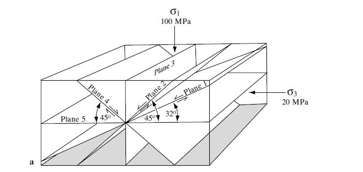
Step by Step Answer:

This question has not been answered yet.
You can Ask your question!
Related Book For 
Structural Analysis And Synthesis A Laboratory Course In Structural Geology
ISBN: 9781405116527
3rd Edition
Authors: Stephen M. Rowland, Ernest M. Duebendorfer, Ilsa M. Schiefelbein
Question Posted:
