

An op-amp circuit is shown in Figure P12.22. Its parameters are as described in Problem 12.22, except
Question:
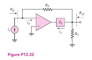
An op-amp circuit is shown in Figure P12.22. Its parameters are as described in Problem 12.22, except that \(R_{i}=2 \mathrm{k} \Omega\) and \(R_{o}=20 \mathrm{k} \Omega\). Determine the closed-loop input and output resistances, \(R_{i f}\) and \(R_{o f}\), respectively.
Data From Problem 12.22:-
Consider the op-amp circuit in Figure P12.22. The op-amp has a finite gain, so that \(i_{o}=A i_{\varepsilon}\), and a zero output impedance.
(a) Write the closed-loop transfer function in the form \[A_{i f}=\frac{i_{o}}{i_{s}}=\frac{A_{i}}{\left(1+\beta_{i} A_{i}\right)}\]
(b) What is the expression for \(\beta_{i}\) ?
(c) If \(A_{i}=10^{5}\) and \(A_{i f}=25\), what is the required \(\beta_{i}\) and \(R_{F} / R_{3}\) ?
(d) If \(A_{i}\) decreases by 15 percent, what is the percent change in \(A_{i f}\) ?
Step by Step Answer:


Microelectronics Circuit Analysis And Design
ISBN: 9780071289474
4th Edition
Authors: Donald A. Neamen
