

Consider the differential amplifier shown in Figure P11.13 with mismatched collector resistors. The circuit and transistor parameters
Question:
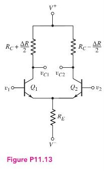
Consider the differential amplifier shown in Figure P11.13 with mismatched collector resistors. The circuit and transistor parameters are \(V^{+}=5 \mathrm{~V}\), \(V^{-}=-5 \mathrm{~V}, \beta=120, V_{B E}(\) on \()=0.7 \mathrm{~V}\), and \(V_{A}=\infty\).
(a) For \(\Delta R=0\), design the circuit such that \(I_{C Q 1}=I_{C Q 2}=120 \mu \mathrm{A}\) and \(v_{C 1}=v_{C 2}=3 \mathrm{~V}\) for \(v_{1}=v_{2}=0\).
(b) Using the results of part (a), determine \(\left|A_{d}\right|\) for a twosided output.
(c) For \(\Delta R=500 \Omega\), determine \(A_{d}, A_{c m}\), and \(\mathrm{CMRR}_{\mathrm{dB}}\) for \(v_{o}=\Delta\left(v_{C 1}-v_{C 2}\right)\)
Fantastic news! We've Found the answer you've been seeking!
Step by Step Answer:

Answered By
Shehar bano
I have collective experience of more than 7 years in education. my area of specialization includes economics, business, marketing and accounting. During my study period I remained engaged with a business school as a visiting faculty member and did a lot of business research. I am also tutoring and mentoring number of international students and professionals online for the last 7 years.
4+ Reviews
10+ Question Solved
Related Book For 

Microelectronics Circuit Analysis And Design
ISBN: 9780071289474
4th Edition
Authors: Donald A. Neamen
Question Posted:
