

Consider the MC14573 op-amp in Figure 13.14. The dc bias currents and small-signal voltage gains were determined
Question:
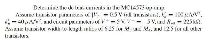
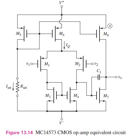
Consider the MC14573 op-amp in Figure 13.14. The dc bias currents and small-signal voltage gains were determined in Examples 13.8 and 13.9. Redesign the circuit such that the width-to-length ratio of \(M_{1}\) and \(M_{2}\) is increased from 12.5 to 50 . All other circuit and transistor parameters remain the same.
(a) Determine the original transconductance of \(M_{1}\) and \(M_{2}\), and the new transconductance value.
(b) Determine the new values of voltage gain for the input and second stages, and the overall voltage gain.
Data From Example 13.8:-
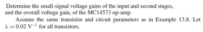
Data From Example 13.9:-
Fantastic news! We've Found the answer you've been seeking!
Step by Step Answer:

Answered By
Dorcas Juliet
I am a proficient tutor and writer with over 4 years experience, I can deliver A+ works in all fields related to business and economics subject. Kindly hire me for excellent papers
10+ Reviews
51+ Question Solved
Related Book For 

Microelectronics Circuit Analysis And Design
ISBN: 9780071289474
4th Edition
Authors: Donald A. Neamen
Question Posted:
