

Consider the simple series-pass regulator circuit in Figure P15.88. Assume an ideal Zener diode with (V_{Z}=V_{mathrm{REF}}=4.7 mathrm{~V}).
Question:
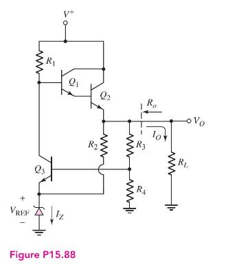
Consider the simple series-pass regulator circuit in Figure P15.88. Assume an ideal Zener diode with \(V_{Z}=V_{\mathrm{REF}}=4.7 \mathrm{~V}\). Let \(\beta=100\) and \(V_{B E}(\) on \()=0.7 \mathrm{~V}\) for all transistors.
(a) Design the circuit such that \(V_{O}=10 \mathrm{~V}\) and \(I_{Z}=10 \mathrm{~mA}\) for a nominal supply voltage of \(V^{+}=20 \mathrm{~V}\).
(b) Determine the regulator output resistance \(R_{o f}\).
Fantastic news! We've Found the answer you've been seeking!
Step by Step Answer:

Answered By
Pushpinder Singh
Currently, I am PhD scholar with Indian Statistical problem, working in applied statistics and real life data problems. I have done several projects in Statistics especially Time Series data analysis, Regression Techniques.
I am Master in Statistics from Indian Institute of Technology, Kanpur.
I have been teaching students for various University entrance exams and passing grades in Graduation and Post-Graduation.I have expertise in solving problems in Statistics for more than 2 years now.I am a subject expert in Statistics with Assignmentpedia.com.
3+ Reviews
10+ Question Solved
Related Book For 

Microelectronics Circuit Analysis And Design
ISBN: 9780071289474
4th Edition
Authors: Donald A. Neamen
Question Posted:
