

The circuit parameters for the class-A emitter follower shown in Figure P8.16 are (V^{+}=24 mathrm{~V}, V^{-}=-24 mathrm{~V}),
Question:
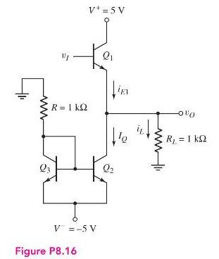
The circuit parameters for the class-A emitter follower shown in Figure P8.16 are \(V^{+}=24 \mathrm{~V}, V^{-}=-24 \mathrm{~V}\), and \(R_{L}=200 \Omega\). The transistor parameters are \(\beta=50, V_{B E}(\mathrm{on})=0.7 \mathrm{~V}\), and \(V_{C E}(\mathrm{sat})=0.2 \mathrm{~V}\). The output voltage is to vary between \(+20 \mathrm{~V}\) and \(-20 \mathrm{~V}\). The minimum current in \(Q_{1}\) is to be \(i_{E 1}=20 \mathrm{~mA}\).
(a) Find the minimum required \(I_{Q}\) and the minimum value of \(R\).
(b) For \(v_{O}=0\), find the power dissipated in the transistor \(Q_{1}\) and the power dissipated in the current source \(\left(Q_{2}, Q_{3}\right.\), and \(R\) ).
(c) Determine the conversion efficiency for a symmetrical sine-wave output voltage with a peak value of \(20 \mathrm{~V}\).
Step by Step Answer:


Microelectronics Circuit Analysis And Design
ISBN: 9780071289474
4th Edition
Authors: Donald A. Neamen
