

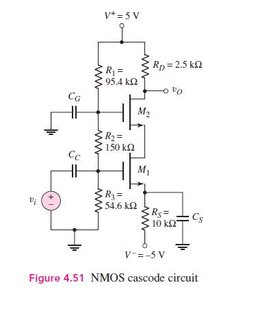
The supply voltages to the cascode circuit in Figure 4.51 in the text are changed to (V^{+}=10
Question:
The supply voltages to the cascode circuit in Figure 4.51 in the text are changed to \(V^{+}=10 \mathrm{~V}\) and \(V^{-}=-10 \mathrm{~V}\). The transistor parameters are: \(K_{n 1}=K_{n 2}=4 \mathrm{~mA} / \mathrm{V}^{2}, V_{T N 1}=V_{T N 2}=1.5 \mathrm{~V}\), and \(\lambda_{1}=\lambda_{2}=0\).
(a) Let \(R_{S}=2 \mathrm{k} \Omega\), and assume the current in the bias resistors is \(0.1 \mathrm{~mA}\). Design the circuit such that \(I_{D Q}=5 \mathrm{~mA}\) and \(V_{D S Q 1}=V_{D S Q 2}=3.5 \mathrm{~V}\).
(b) Determine the resulting small-signal voltage gain.
Fantastic news! We've Found the answer you've been seeking!
Step by Step Answer:
a R1388 mathrmk O...View the full answer

Answered By
Divya Munir
I hold M.Sc and M.Phil degrees in mathematics from CCS University, India and also have a MS degree in information management from Asian institute of technology, Bangkok, Thailand. I have worked at a international school in Bangkok as a IT teacher. Presently, I am working from home as a online Math/Statistics tutor. I have more than 10 years of online tutoring experience. My students have always excelled in their studies.
0 Reviews
10+ Question Solved
Related Book For 

Microelectronics Circuit Analysis And Design
ISBN: 9780071289474
4th Edition
Authors: Donald A. Neamen
Question Posted:
