

A more complicated model of the armature-controlled motor is shown in Figure 6.51, in which the rotor
Question:
A more complicated model of the armature-controlled motor is shown in Figure 6.51, in which the rotor is connected to an inertial load through a flexible and damped shaft. \(K_{\mathrm{m}}\) and \(B_{\mathrm{m}}\) represent the torsional stiffness and the torsional viscous damping of the shaft, respectively. The mass moments of inertia of the motor and the load are \(I_{\mathrm{m}}\) and \(I_{\mathrm{L}}\), respectively. Let \(\omega_{\mathrm{m}}=\dot{\theta}_{\mathrm{m}}\) and \(\omega_{\mathrm{L}}=\dot{\theta}_{\mathrm{L}}\).
a. Assuming zero initial conditions, derive the transfer functions \(\Omega_{\mathrm{L}}(s) / V_{\mathrm{a}}(s)\) and \(\Omega_{\mathrm{L}}(\mathrm{s}) / T_{\mathrm{L}}(\mathrm{s})\).
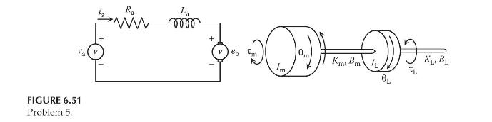
b. Assuming the angular velocity \(\omega_{\mathrm{L}}\) to be the output, draw a block diagram to represent the dynamics of the armature-controlled motor.
c. Determine the state-space form.
Step by Step Answer:

This question has not been answered yet.
You can Ask your question!

Modeling And Analysis Of Dynamic Systems
ISBN: 9781138726420
3rd Edition
Authors: Ramin S. Esfandiari, Bei Lu
