

Consider the electrical circuit in Figure 7.6, where the input (u(t)) is a voltage and the output
Question:
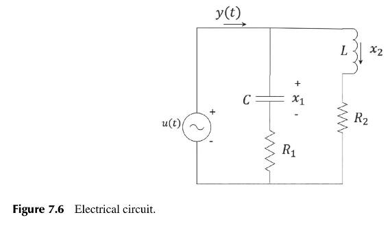
Consider the electrical circuit in Figure 7.6, where the input \(u(t)\) is a voltage and the output \(y(t)\) is the total current flowing through the capacitor and inductor as indicated.
(a) Explain why the state variables should be chosen as \(x_{1}=v_{C}\) and \(x_{2}=i_{L}\).
(b) Write down state-variable equations for the system, and deduce the system's State-Space model \((A, B, C, D)\).
(c) Explain the concepts of controllability and observability. How are these properties determined for a system whose model is given by matrices \((A, B, C, D)\) ?
(d) What conditions relating \(R_{1}, R_{2}, L\) and \(C\) will render the system uncontrollable?
(e) What conditions relating \(R_{1}, R_{2}, L\) and \(C\) will render the system unobservable?
(f) For the State-Space model derived in (b), if \(R_{1}=R_{2}=5\) and \(L=C=1\), design a block diagram for the circuit with one integrator for each state variable.
(g) Derive the circuit's transfer function using matrix algebra.
Step by Step Answer:
a The variables vC and iL are chosen because the capacitor and inductor are the two energystoring elements in the system Whenever we are dealing with a capacitor or an inductor the starting point is a...View the full answer


Design And Analysis Of Control Systems Driving The Fourth Industrial Revolution
ISBN: 9781032718804
2nd Edition
Authors: Arthur G O Mutambara
