

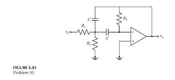
Repeat Problem 9 for the op-amp circuit shown in Figure 6.81, which represents an active band-pass filter.
Question:
Repeat Problem 9 for the op-amp circuit shown in Figure 6.81, which represents an active band-pass filter.
Data From Problem 9:
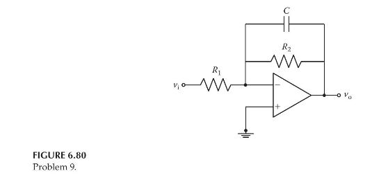
The op-amp circuit shown in Figure 6.80 is an active low-pass filter. Derive the input-output differential equation relating the output voltage \(v_{0}(t)\) and the input voltage \(v_{\mathrm{i}}(t)\). Assuming zero initial conditions, find the transfer function \(V_{\mathrm{o}}(s) / V_{\mathrm{i}}(s)\) directly from the input-output equation.
Fantastic news! We've Found the answer you've been seeking!
Step by Step Answer:

Answered By
Vincent Omondi
I am an extremely self-motivated person who firmly believes in his abilities. With high sensitivity to task and operating parameters, deadlines and keen on instructions, I deliver the best quality work for my clients. I handle tasks ranging from assignments to projects.
109+ Reviews
314+ Question Solved
Related Book For 

Modeling And Analysis Of Dynamic Systems
ISBN: 9781138726420
3rd Edition
Authors: Ramin S. Esfandiari, Bei Lu
Question Posted:
