

A single-line diagram of a four-bus system is shown in Figure 9.27 . Equipment ratings and per-unit
Question:
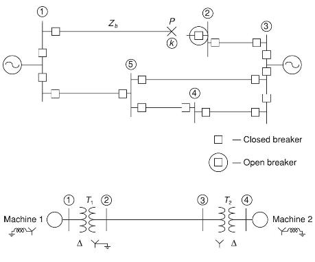
A single-line diagram of a four-bus system is shown in Figure 9.27 . Equipment ratings and per-unit reactances are given as follows.
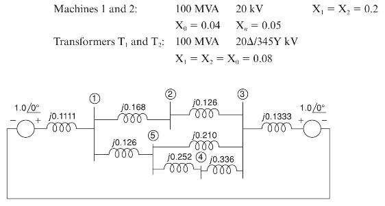
On a base of \(100 \mathrm{MVA}\) and \(345 \mathrm{kV}\) in the zone of the transmission line, the series reactances of the transmission line are \(X_{1}=X_{2}=0.15\) and \(X_{0}=0.5\) per unit.
(a) Draw each of the sequence networks and determine the bus impedance matrix for each of them.
(b) Assume the system to be operating at nominal system voltage without prefault currents when a bolted line-to-line fault occurs at bus 3. Compute the fault current, the line-to-line voltages at the faulted bus, and the line-to-line voltages at the terminals of machine 2.
(c) Assume the system to be operating at nominal system voltage without prefault currents, when a bolted double line-toground fault occurs at the terminals of machine 2. Compute the fault current and the line-to-line voltages at the faulted bus.
Step by Step Answer:

This question has not been answered yet.
You can Ask your question!


Power System Analysis And Design
ISBN: 9781305632134
6th Edition
Authors: J. Duncan Glover, Thomas Overbye, Mulukutla S. Sarma
