

As shown in Figure 13.32, a single-phase two-wire lossless line with (Z_{c}=) (400 Omega, v=3 times 10^{8}
Question:
As shown in Figure 13.32, a single-phase two-wire lossless line with \(Z_{c}=\) \(400 \Omega, v=3 \times 10^{8} \mathrm{~m} / \mathrm{s}\), and \(1=100 \mathrm{~km}\) has a \(400-\Omega\) resistor, denoted \(\mathrm{R}_{\mathrm{J}}\), installed across the center of the line, thereby dividing the line into two sections, \(\mathrm{A}\) and \(\mathrm{B}\). The source voltage at the sending end is a pulse of magnitude \(100 \mathrm{~V}\) and duration \(0.1 \mathrm{~ms}\). The source impedance is \(\mathrm{Z}_{\mathrm{G}}=Z_{c}=\) \(400 \Omega\), and the receiving end of the line is short-circuited,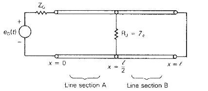
(a) Show that for an incident voltage wave arriving at the center of the line from either line section, the voltage reflection and refraction coefficients are given by \(\Gamma_{\mathrm{BB}}=\Gamma_{\mathrm{AA}}=\frac{\left(\frac{Z_{\mathrm{eq}}}{Z_{c}}ight)-1}{\left(\frac{Z_{\mathrm{eq}}}{Z_{c}}ight)+1} \quad \Gamma_{\mathrm{AB}}=\Gamma_{\mathrm{BA}}=\frac{2\left(\frac{Z_{\mathrm{eq}}}{Z_{c}}ight)}{\left(\frac{Z_{\mathrm{eq}}}{Z_{c}}ight)+1}\)
where \(\mathrm{Z}_{\mathrm{eq}}=\frac{R_{\mathrm{J}} \mathrm{Z}_{c}}{\mathrm{R}_{\mathrm{J}}+\mathrm{Z}_{c}}\)
(b) Draw the Bewley lattice diagram for \(0 \leq t \leq 6 \tau\).
(c) Plot \(v(1 / 2, t)\) versus time \(t\) for \(0 \leq t \leq 6 \tau\) and plot \(v(x, 6 \tau)\) versus \(x\) for \(0 \leq x \leq l\).
Step by Step Answer:

This question has not been answered yet.
You can Ask your question!


Power System Analysis And Design
ISBN: 9781305632134
6th Edition
Authors: J. Duncan Glover, Thomas Overbye, Mulukutla S. Sarma
