

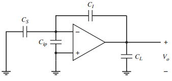
The feedback circuit in Fig. 9.55 is a switched-capacitor circuit during one clock phase. Assume the op
Question:
Assume the op amp is the telescopic-cascode op amp in Fig. 9.54. Take CL= 1.5 pF, CI = 4 pF, CS = 0.4 pF, and Cip = 0.1 pF.
(a) If ITAIL= 0.2 mA, what is the output slew rate?
(b) Assume that gm1= 0.1 mA/V, the loop trans-mission [loop gainT(s) or return ratio R(s)] can be modeled as having two poles, and the magnitude of the nondominant pole p2 is |p2| = 200 Mrad/s.
What is the phase margin of this feedback circuit?
Figure 9.55:
Fantastic news! We've Found the answer you've been seeking!
Step by Step Answer:
a The equivalent load is C L C L C I C S C ip 15 4 04 01 19 pF SR 02m...View the full answer

Answered By
Muhammad Umair
I have done job as Embedded System Engineer for just four months but after it i have decided to open my own lab and to work on projects that i can launch my own product in market. I work on different softwares like Proteus, Mikroc to program Embedded Systems. My basic work is on Embedded Systems. I have skills in Autocad, Proteus, C++, C programming and i love to share these skills to other to enhance my knowledge too.
1+ Reviews
10+ Question Solved
Related Book For 

Analysis and Design of Analog Integrated Circuits
ISBN: 978-0470245996
5th edition
Authors: Paul R. Gray, Paul J. Hurst Stephen H. Lewis, Robert G. Meyer
Question Posted:
