

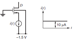
The transistor shown in Fig. 2.74 is connected in the circuit shown in Fig. 2.75. The gate
Question:
Fig. 2.74
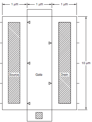
Fig. 2.75
Fantastic news! We've Found the answer you've been seeking!
Step by Step Answer:
V D t 0 V s t 0 15 v i Intially transistor is off current source discharges C oL C SB ...View the full answer

Answered By
Branice Buyengo Ajevi
I have been teaching for the last 5 years which has strengthened my interaction with students of different level.
1+ Reviews
10+ Question Solved
Related Book For 

Analysis and Design of Analog Integrated Circuits
ISBN: 978-0470245996
5th edition
Authors: Paul R. Gray, Paul J. Hurst Stephen H. Lewis, Robert G. Meyer
Question Posted:
