

In a typical microprocessor ALU, the results of every arithmetic operation are usually (but not always) transferred
Question:
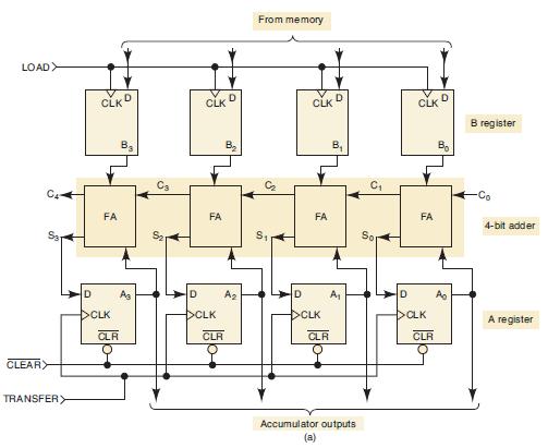
In a typical microprocessor ALU, the results of every arithmetic operation are usually (but not always) transferred to the accumulator register, as in Figures 6-10 and 6-14. In most microprocessor ALUs, the result of each arithmetic operation is also used to control the states of several special flip-flops called flags. These flags are used by the microprocessor when it is making decisions during the execution of certain types of instructions. The three most common flags are:
S (sign flag). This FF is always in the same state as the sign of the last result from the ALU.
Z (zero flag). This flag is set to 1 whenever the result from an ALU operation is exactly 0. Otherwise, it is cleared to 0.
C (carry flag). This FF is always in the same state as the carry from the MSB of the ALU.
Using the adder/subtractor of Figure 6-14 as the ALU, design the logic circuit that will implement these flags. The sum outputs and C4 output are to be used to control what state each flag will go to upon the occurrence of the TRANSFER pulse. For example, if the sum is exactly 0 (i.e., 0000), the Z flag should be set by the PGT of TRANSFER; otherwise, it should be cleared.
Figure 6-14
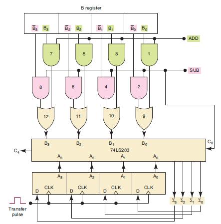
Figure 6-10
Step by Step Answer:


Digital Systems Principles And Application
ISBN: 9780134220130
12th Edition
Authors: Ronald Tocci, Neal Widmer, Gregory Moss
