

Refer to Figure 7-119 to answer the following questions: (a) Which register function (load or shift) will
Question:
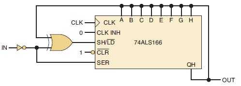
Refer to Figure 7-119 to answer the following questions:
(a) Which register function (load or shift) will be performed on the next clock if in = 1 and out = 0? What data value will be input when clocked?
(b) Which register function (load or shift) will be performed on the next clock if in = 0 and out = 1? What data value will be input when clocked?
(c) Which register function (load or shift) will be performed on the next clock if in = 0 and out = 0? What data value will be input when clocked?
(d) Which register function (load or shift) will be performed on the next clock if in = 1 and out = 1? What data value will be input when clocked?
(e) What input condition will eventually (after several clock pulses)
cause the output to switch states?
(f) To change the output logic level requires the new input condition to last for at least how many clock pulses?
(g) If the input signal changes levels and then goes back to its original logic level before the number of clock pulses specified in part
(f), what happens to the output signal.
(h) Explain why this circuit can be used to debounce switches.
Figure 7-119
Step by Step Answer:


Digital Systems Principles And Application
ISBN: 9780134220130
12th Edition
Authors: Ronald Tocci, Neal Widmer, Gregory Moss
