

For the programmable logic block shown in Figure 5-13, show the necessary configuration settings to implement each
Question:
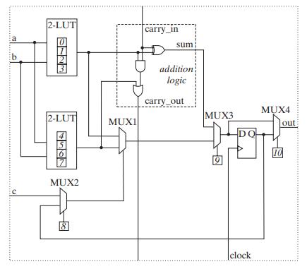
For the programmable logic block shown in Figure 5-13, show the necessary configuration settings to implement each of the following types of circuits. You can assume that the upper data input of each multiplexer is chosen with a select input of 0.
(a) A combinational function of inputs a, b, and c.
(b) A Moore machine
(c) A Mealy machine
Figure 5-13
Fantastic news! We've Found the answer you've been seeking!
Step by Step Answer:
Heres how we can configure the block for each scenario a Combinational Function of Inputs a b and c ...View the full answer

Answered By
Rayan Gilbert
I have been teaching since I started my graduation 3 years ago. As a student, working as Teacher/PA has been tough but made me learn the needs for student and how to help them resolve their problems efficiently. I feel good to be able to help out students because I'm passionate about teaching. My motto for teaching is to convey the knowledge I have to students in a way that makes them understand it without breaking a sweat.
1+ Reviews
10+ Question Solved
Related Book For 

Logic And Computer Design Fundamentals
ISBN: 9780133760637
5th Edition
Authors: M. Morris Mano, Charles Kime, Tom Martin
Question Posted:
