

Consider the simple bipolar op-amp circuit shown in Figure P13.2. The bias current is (I_{Q}=0.5 mathrm{~mA}). Transistor
Question:
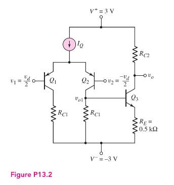
Consider the simple bipolar op-amp circuit shown in Figure P13.2. The bias current is \(I_{Q}=0.5 \mathrm{~mA}\). Transistor parameters are \(\beta_{n}=180, \beta_{p}=120\), \(V_{B E}\) (on) \(=V_{E B}\) (on) \(=0.7 \mathrm{~V}\), and \(V_{A n}=V_{A p}=\infty\).
(a) Design the circuit such that \(I_{C 3}=0.4 \mathrm{~mA}\) and \(v_{o}=0\) when \(v_{1}=v_{2}=0\).
(b) Find the smallsignal voltage gains (i) \(A_{d}=v_{o 1} / v_{d}\) and (ii) \(A_{2}=v_{o} / v_{o 1}\).
(c) Determine the overall small-signal voltage gain \(A=v_{o} / v_{d}\).
Fantastic news! We've Found the answer you've been seeking!
Step by Step Answer:

Answered By
S Mwaura
A quality-driven writer with special technical skills and vast experience in various disciplines. A plagiarism-free paper and impeccable quality content are what I deliver. Timely delivery and originality are guaranteed. Kindly allow me to do any work for you and I guarantee you an A-worthy paper.
27+ Reviews
73+ Question Solved
Related Book For 

Microelectronics Circuit Analysis And Design
ISBN: 9780071289474
4th Edition
Authors: Donald A. Neamen
Question Posted:
