

In the switched-capacitor circuit in Figure 15.12(a), the voltages are (V_{1}=2 mathrm{~V}) and (V_{2}=1 mathrm{~V}), the capacitor
Question:
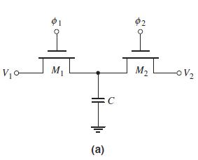
In the switched-capacitor circuit in Figure 15.12(a), the voltages are \(V_{1}=2 \mathrm{~V}\) and \(V_{2}=1 \mathrm{~V}\), the capacitor value is \(C=10 \mathrm{pF}\), and the clock frequency is \(f_{C}=100 \mathrm{kHz}\).
(a) Determine the charge transferred from \(V_{1}\) to \(V_{2}\) during each clock pulse.
(b) What is the average current that source \(V_{1}\) supplies?
(c) If the "on" resistance of each MOSFET is \(1000 \Omega\), determine the time required to transfer 99 percent of the charge during each half-clock period.
Figure 15.12(a):-
Fantastic news! We've Found the answer you've been seeking!
Step by Step Answer:

Answered By
Carly Cimino
As a tutor, my focus is to help communicate and break down difficult concepts in a way that allows students greater accessibility and comprehension to their course material. I love helping others develop a sense of personal confidence and curiosity, and I'm looking forward to the chance to interact and work with you professionally and better your academic grades.
12+ Reviews
21+ Question Solved
Related Book For 

Microelectronics Circuit Analysis And Design
ISBN: 9780071289474
4th Edition
Authors: Donald A. Neamen
Question Posted:
