

Design Project: The closed-loop control system of the DC motor can be derived and shown to be
Question:
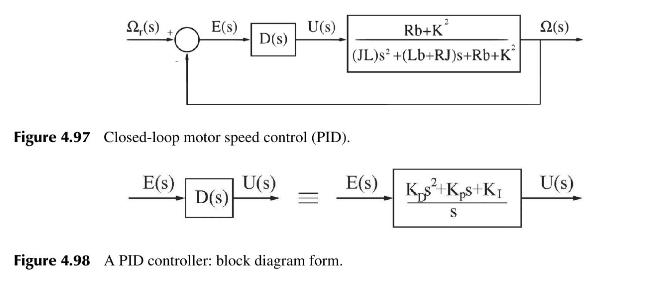
Design Project: The closed-loop control system of the DC motor can be derived and shown to be given by Figure 4.97. The terms \(\Omega(s), \Omega_{r}(s)\) are the Laplace transforms of the actual angular speed \(w(t)\) and the desired angular speed \(w_{r}(t)\), respectively. \(E(s)\) and \(U(s)\) are the Laplace transforms of the error and the control signals.
The controller \(D(s)\) can take the form of any one of the four controllers \(P, P I, P D\), and PID. A PID controller contains all three control components (proportional, derivative, and integral) and hence, its transfer function can be represented as follows:
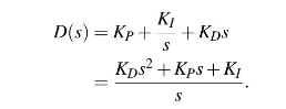
Thus, the corresponding block diagram representation takes the form shown in Figure 4.98. This is the generic PID controller, and the other controllers P, PI,PD can be modelled in a similar fashion.
(a) Characteristics of PID Controllers By employing MATLAB, implement four closed-loop control systems for the DC motor by using the four controllers ( P, PI, PD, and PID) and the data provided. The objective is to satisfy the given
design requirements. From the results discuss the benefits and drawbacks of the controller components; Proportional (P), Integral (I), and Derivative \((D)\). Also, show and explain how the three components compensate for each other's drawbacks.
(b) Tuning of PID Controllers From the MATLAB implementation explain how you choose the gains \(\left(K_{P}, K_{I}, K_{D}ight)\) for the controllers (P, PI, PD and PID).
DATA Assume the following values for the physical parameters, which were derived by experiment from an actual motor:
Moment of inertia of the rotor \(J=0.012 \mathrm{~kg} \mathrm{~m}^{2}\)
Damping ratio of the mechanical system \(b=0.105 \mathrm{Nm} \mathrm{s}\)
Electromotive force constant \(K=0.01 \mathrm{Nm} / \mathrm{A}\)
Electric resistance \(R=1 \Omega\)
Electric inductance \(L=0.505 \mathrm{H}\)
DESIGN REQUIREMENTS Desired angular speed \(w_{r}(t)=1 \mathrm{rad} / \mathrm{sec}\)
Settling time \(t_{s}=1 \mathrm{sec}\)
Overshoot \(M_{p} \leq 20 \%\)
Steady-state error \(e_{s s}(t) \leq 5 \%\)
Step by Step Answer:


Design And Analysis Of Control Systems Driving The Fourth Industrial Revolution
ISBN: 9781032718804
2nd Edition
Authors: Arthur G O Mutambara
