

The truss shown in the figure supports force (F) at node 2 . The finite element method
Question:
The truss shown in the figure supports force \(F\) at node 2 . The finite element method is used to analyze this structure using two truss elements as shown.
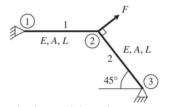
a. Compute the transformation matrix for elements 1 and 2.
b. Compute the element stiffness matrices for both elements in the global coordinate
system.
c. Assemble the element stiffness matrices and force vectors to the structural matrix equation \(\left[\mathbf{K}_{s}ight]\left\{\mathbf{Q}_{s}ight\}=\left\{\mathbf{F}_{s}ight\}\) before applying boundary conditions.
d. Solve the FE equation after applying the boundary conditions. Write nodal displacements in the global coordinates.
e. Compute stress in element 1. Is it tensile or compressive?
Step by Step Answer:


Introduction To Finite Element Analysis And Design
ISBN: 9781119078722
2nd Edition
Authors: Nam H. Kim, Bhavani V. Sankar, Ashok V. Kumar
