

The truss structure shown in the figure supports a force (F). The finite element method is used
Question:
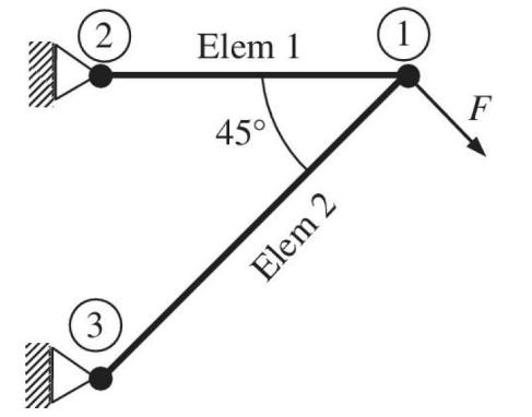
The truss structure shown in the figure supports a force \(F\). The finite element method is used to analyze this structure using two truss elements as shown in the figure. The cross sectional area for both elements is \(A=2 \mathrm{in}^{2}\), and the lengths are \(L^{(2)}=10 \mathrm{ft}\). Young's Modulus of the material \(\mathrm{E}=30 \times 10^{6} \mathrm{psi}\).
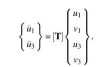
a. Compute the transformation matrix [T] for element 2 that enables you to transform between global and local coordinates (as shown in equation below).
b. It is determined after solving the final equations that the displacement components of the node 1 are: \(u_{1}=0.5 \times 10^{-2} \mathrm{in}\). and \(v_{1}=-1.5 \times 10^{-2} \mathrm{in}\). What are the strain, stress, and force in element 2 ?
Step by Step Answer:


Introduction To Finite Element Analysis And Design
ISBN: 9781119078722
2nd Edition
Authors: Nam H. Kim, Bhavani V. Sankar, Ashok V. Kumar
