

The truss structure shown in the figure supports the force (F). The finite element method is used
Question:
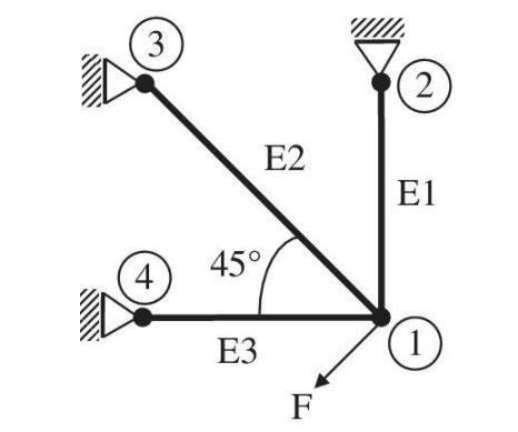
The truss structure shown in the figure supports the force \(F\). The finite element method is used to analyze this structure using three truss elements as shown. The area of cross section (for all elements) \(A=2\) in \(^{2}\). Young's Modulus \(E=30 \times 10^{6} \mathrm{psi}\). The lengths of the elements are: \(L_{1}=L_{3}=10 \mathrm{ft}\)., \(L_{2}=14.14 \mathrm{ft}\).
a. Determine the stiffness matrix of element 2 .
b. It is determined after solving the final equations that the displacement components of node 1 are: \(u_{1}=-0.5 \times 10^{-2}\) in. and \(v_{1}=-1.5 \times 10^{-2}\) in. Using the four equations for this element, compute the forces acting on element 2 at nodes 1 and 3 . Are these two forces collinear?
c. What is the change in length of element 2?
Step by Step Answer:


Introduction To Finite Element Analysis And Design
ISBN: 9781119078722
2nd Edition
Authors: Nam H. Kim, Bhavani V. Sankar, Ashok V. Kumar
