

For the three-phase power system with single-line diagram shown in Figure 9.22, equipment ratings and per-unit reactances
Question:
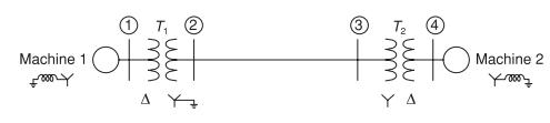
For the three-phase power system with single-line diagram shown in Figure 9.22, equipment ratings and per-unit reactances are given as follows:
Machines 1 and 2: \(\quad 100\) MVA \(20 \mathrm{kV} \quad \mathrm{X}_{1}=\mathrm{X}_{2}=0.2\) \[ \mathrm{X}_{0}=0.04 \quad \mathrm{X}_{n}=0.04 \]
Transformers 1 and 2: \(100 \mathrm{MVA} 20 \Delta / 345 \mathrm{Y} \mathrm{kV}\) \[ X_{1}=X_{2}=X_{0}=0.08 \]
Select a base of \(100 \mathrm{MVA}, 345 \mathrm{kV}\) for the transmission line. On that base, the series reactances of the line are \(X_{1}=X_{2}=0.15\) and \(X_{0}=0.5\) per unit. With a nominal system voltage of \(345 \mathrm{kV}\) at bus 3, machine 2 is operating as a motor drawing \(50 \mathrm{MVA}\) at 0.8 power factor lagging. Compute the change in voltage at bus 3 when the transmission line undergoes
(a) a one-conductor-open fault,
(b) a two-conductor-open fault along its span between buses 2 and 3.
Figure 9.22
Step by Step Answer:


Power System Analysis And Design
ISBN: 9781305632134
6th Edition
Authors: J. Duncan Glover, Thomas Overbye, Mulukutla S. Sarma
