

The circuit of Figure P7=50 is a two-stage circuit that will be studied extensively in Chapter 12
Question:
The circuit of Figure P7=50 is a two-stage circuit that will be studied extensively in Chapter 12 as a band-pass filter. It is a second-order circuit whose zero-state step response can be solved by recognizing that since \(R\) and \(C\) are the same, the solution fits Case B for the natural response \(v_{2 \mathrm{~N}}(t)\) ( Eq-7-6 \(5 \underline{\mathrm{b}}\) .) Caution: \(v_{2}(t)\) is not \(v_{\mathrm{C}}(t)\) in the second circuit.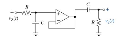
(a) Find the output \(v_{2}(t)\) when the input \(v_{\mathrm{S}}(t)=6 u(t\) ), \(R=15 \mathrm{k} \Omega\), and \(C=0.1 \mu \mathrm{F}\).
(b) Use MATLAB to plot your result.
(c) Simulate the circuit using Multisim and compare your results.
Step by Step Answer:
a b c Find the voltage across the left capacitor The voltage is a step ...View the full answer


The Analysis And Design Of Linear Circuits
ISBN: 9781119913023
10th Edition
Authors: Roland E. Thomas, Albert J. Rosa, Gregory J. Toussaint
