

The circuit of Figure P7=51 is a two-stage, firstorder cascade circuit that will be studied extensively in
Question:
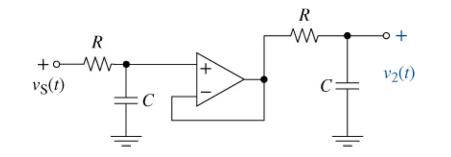
The circuit of Figure P7=51 is a two-stage, firstorder cascade circuit that will be studied extensively in Chapter 14. It is a second-order circuit whose zero-state step response can be solved by recognizing that since R and C are the same, the solution fits Case B for the natural response v2 N(t) ( Eq.7二 65b. ) Note both the similarity and the difference between the circuit in Figure P7-50 and Figure P7=51. As we will study later, the former is a band-pass filter, while the latter is a secondorder low-pass filter.
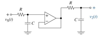
(a) For the circuit in Figure P7=51 find the output v2(t) when the input vS(t)=5u(t),R=10kΩ, and C=0.1μF.
(b) Use MATLAB to plot your result.
(c) Simulate together both the filter in Figure P7=50 and that in Figure P7=51 using Multisim. Note that both filters have similar component values and input step functions. What conclusions can you draw about the step responses of these circuits?


Step by Step Answer:
a b c The OP AMP isolates the two RC circuits from each other Let u1 be the voltage ac...View the full answer


The Analysis And Design Of Linear Circuits
ISBN: 9781119913023
10th Edition
Authors: Roland E. Thomas, Albert J. Rosa, Gregory J. Toussaint
