

Question: Consider the circuit shown in Figure B2 (b), assuming - Vad = 3.3 V, L = 1 m, W= 100 m, k, = 40
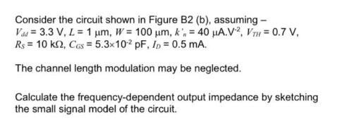
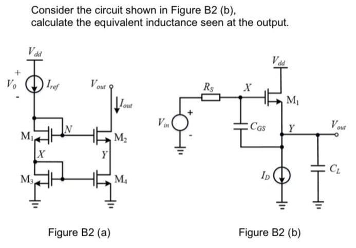
Consider the circuit shown in Figure B2 (b), assuming - Vad = 3.3 V, L = 1 m, W= 100 m, k, = 40 A.V2, VTH = 0.7 V, Rs = 10 k2, CGs = 5.3x10² pF, Ip = 0.5 mA. The channel length modulation may be neglected. Calculate the frequency-dependent output impedance by sketching the small signal model of the circuit. Vo Consider the circuit shown in Figure B2 (b), calculate the equivalent inductance seen at the output. Vdd M, M X Iref N Vout Y Figure B2 (a) Lout M M Vin Rs X CGS ID Vad M Y Figure B2 (b) Vout CL
Step by Step Solution
★★★★★
3.57 Rating (157 Votes )
There are 3 Steps involved in it
1 Expert Approved Answer
Step: 1 Unlock

Question Has Been Solved by an Expert!
Get step-by-step solutions from verified subject matter experts
Step: 2 Unlock
Step: 3 Unlock