

Question: Demonstrating Inductance. A common demonstration of inductance employs a circuit such as the one shown in Fig. 30.27. Switch S is closed, and the light
Demonstrating Inductance. A common demonstration of inductance employs a circuit such as the one shown in Fig. 30.27. Switch S is closed, and the light bulb (represented by resistance R1) just barely glows. After a period of time, switch S is opened, and the bulb lights up brightly for a short period of time. To understand this effect, think of an inductor as a device that imparts an "inertia" to the current, preventing a discontinuous change in the current through it.(a) Derive, as explicit functions of time, expressions for i, (the current through the light bulb) and i1 (the current through the inductor) after switch S is closed.(b) After a long period of time, the currents i, and i, reach their steady-state values. Obtain expressions for these steady-state currents.(c) Switch S is now opened. Obtain an expression for the current through the inductor and light bulb as an explicit function of time.(d) You have been asked to design a demonstration apparatus using the circuit shown in Fig. 30.27 with a 22.0-H inductor and a 40.0-W light bulb. You are to connect a resistor in series with the inductor. and R, represents the sum of that resistance plus the internal resistance of the inductor. When switch S is opened. a transient current is to be set up that starts at 0.600 A and is not to fall below 0.150 A until after 0.0800 s. For simplicity. Assume that the resistance of the light bulb is constant and equals the resistance the bulb must have to dissipate 40.0 W at 120 V. Determine R, and e for the given design considerations.(e) With the numerical values determined in part (d), what is the current through the light bulb just before the switch is opened? Does this result confirm the qualitative description of what is observed in thedemonstration?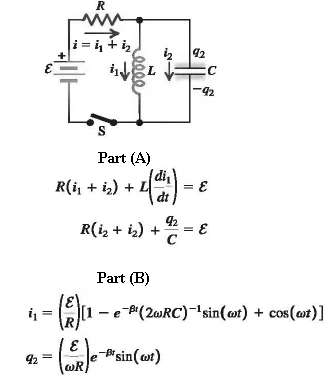
92= R |i=i+h, in reeee R(i + 1) + WR S Part (A) R(i + i) + L (d) = 92 92 C -92 = = E Part (B) (2)[1 - e-Pi(2wRC)-sin(at) + cos(ar)] R -B* sin(at)
Step by Step Solution
3.35 Rating (173 Votes )
There are 3 Steps involved in it
IDENTIFY Follow the steps specified in the problem SET UP The current in an in... View full answer

Get step-by-step solutions from verified subject matter experts
Document Format (1 attachment)
P-E-I (181).docx
120 KBs Word File