

Question: In this problem we explore another method fur the approximate realization of a matched filter, this time using the simple resistance-capacitance (RC) low-pass filter shown
In this problem we explore another method fur the approximate realization of a matched filter, this time using the simple resistance-capacitance (RC) low-pass filter shown in Figure. The frequency response of this filter is H (?) = 1/1 + j?/?0,?where ?0 = 1/2?RC. The input signal g (t) is a rectangular pulse of amplitude A and duration T. The requirement is to optimize the selection of the 3-dB cutoff frequency ?0 of the filter so that the peak pulse signal-to-noise ratio at the filter output is maximized. With this object the in mind, show that the optimum value of ?0 is 0.2/T, for which the loss in signal-to-noise ratio compared to the matched filter is about 1 dB.
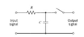
Input signal Output s gnal
Step by Step Solution
3.21 Rating (162 Votes )
There are 3 Steps involved in it
The output of the lowpass RC filter produced by a rectangular pulse of amplitude A and durat... View full answer

Get step-by-step solutions from verified subject matter experts
Document Format (1 attachment)
19-E-T-E-C-S (287).docx
120 KBs Word File